Suzki Burgman AN400. Manual - part 33


  Index      Motorcycles     Suzki Burgman AN400 - service and repair manual 2002 year


Search            


Content   ..  31  32  33  34   ..


Suzki Burgman AN400. Manual - part 33


4-14     FI SYSTEM

SELF-DIAGNOSIS FUNCTION

The self-diagnosis function is incorporated in the ECM. The function has two modes, “User mode” and
“Dealer mode”. The user can only be notified by the LCD (DISPLAY) panel and FI light. To check the func-
tion of the individual FI system devices, the dealer mode is prepared. In this check, the special tool is neces-
sary to read the code of the malfunction items.

USER MODE

*1
When one of the signals is not received by ECM, the fail-safe circuit works and injection is not stopped. In
this case, “FI” and odometer are indicated in the LCD panel and motorcycle can run.
*2
The injection signal is stopped, when the crankshaft position sensor signal, tip over sensor signal, ignition
signal, injector signal, fuel pump relay signal or ignition switch signal is not sent to ECM. In this case, “FI” is
indicated in the LCD panel. Motorcycle does not run.

“CHEC”: The LCD panel indicates “CHEC” when no communication signal from the ECM is received for 5 

seconds.

For Example

: The ignition switch is turned ON, and the engine stop switch is turned OFF. In this case, the speed-

ometer does not receive any signal from ECM, and the panel indicates “CHEC”.
If CHEC is indicated, the LCD does not indicate the trouble code. It is necessary to check the wir-
ing harness between ECM and speedometer couplers.
The possible cause of this indication is as follows;
Engine stop switch is in OFF position. Ignition fuse is burnt.
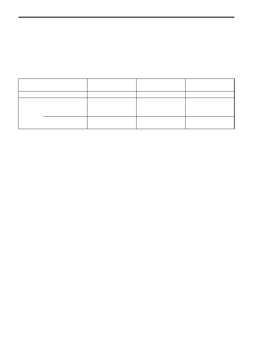
MALFUNCTION

LCD (DISPLAY)

INDICATION

FI LIGHT

INDICATION

INDICATION MODE

“NO”

Odometer

----

----

“YES”

Engine can start

Odometer and
“FI” letters
*1

FI light turns ON.

Each 2 sec. Odometer
or “FI” is indicated.

Engine can not start “FI” letters

*2

FI light turns ON
and blinks.

“FI” is indicated
continuously.

FI SYSTEM     4-15

DEALER MODE

The defective function is memorized in the computer. Use the special tool’s coupler to connect to the dealer
mode coupler. The memorized malfunction code is displayed on LCD (DISPLAY) panel. Malfunction means
that the ECM does not receive signal from the devices. These affected devices are indicated in the code
form.

!

09930-82720: Mode select switch

"

Before checking the malfunction code, do not disconnect the ECM lead wire couplers.
If the couplers from the ECM are disconnected, the malfunction code memory is erased and the
malfunction code can not be checked.

MALFUNCTION

LCD (DISPLAY)

INDICATION

FI LIGHT INDICATION

INDICATION MODE

“NO”

C00

FI light turns OFF.

----

“YES”

C**code is indicated from 
small numeral to large 
one.

For each 2 sec., code is 
indicated.

4-16     FI SYSTEM

In the LCD (DISPLAY) panel, the malfunction code is indicated from small code to large code.

TPS ADJUSTMENT

1. Warm up the engine and adjust the engine idle speed to

1 400 

± 

100 rpm. (

#

2-11)

2. Stop the engine.
3. Connect the special tool (Mode select switch) and select the 

dealer mode.

4. If the throttle position sensor adjustment is necessary, loosen 

the screw and turn the throttle position sensor and bring the 
line to middle.

5. Then, tighten the screw to fix the throttle position sensor.

CODE

MALFUNCTION PART

REMARKS

C00
C12
C13
C14
C15
C21
C23
C24
C32
C40
C41
C42
C44

None
Crankshaft position sensor (CKPS)
Intake air position sensor (IAPS)
Throttle position sensor (TPS)
Engine coolant temperature sensor (ECTS)
Intake air temperature sensor (IATS)
Tip over sensor (TOS)
Ignition signal (IG coil)
Fuel injector signal
Idle air control valve (IAC valve)
Fuel pump control system (FP control system)
Ignition switch signal (IG switch signal)
Heated oxygen sensor (HO2S)

No defective part
Pick-up coil signal, signal generator

Fuel pump, Fuel pump relay
Anti-theft
E-02, 19, 54

Incorrect

Incorrect

Correct position

FI SYSTEM     4-17

FAIL-SAFE FUNCTION

FI system is provided with fail-safe function to allow the engine to start and the motorcycle to run in a mini-
mum performance necessary even under malfunction condition.

The engine can start and can run even if the above signal is not received from each sensor. But, the engine
running condition is not complete, providing only emergency help (by fail-safe circuit). In this case, it is nec-
essary to bring the motorcycle to the workshop for complete repair.

ITEM

FAIL-SAFE MODE

STARTING

ABILTY

RUNNING

ABILITY

Intake air pressure sensor

Intake air pressure is fixed to 760 
mmHg.

“YES”

“YES”

Throttle position sensor

The throttle opening is fixed to full 
open position.
Ignition timing is also fixed.

“YES”

“YES”

Engine coolant temperature 
sensor

Engine coolant temperature value is 
fixed to 80 °C (176 °F).

“YES”

“YES”

Intake air temperature
sensor

Intake air temperature value is fixed 
to 40 °C (104 °F).

“YES”

“YES”

HO2 sensor (E-02, 19, 54 )

Feedback compensation is inhibited.
(Air/fuel ratio is fixed to normal.)

“YES”

“YES”


Content   ..  31  32  33  34   ..