Suzki Burgman AN400. Manual - part 32
4-10 FI SYSTEM
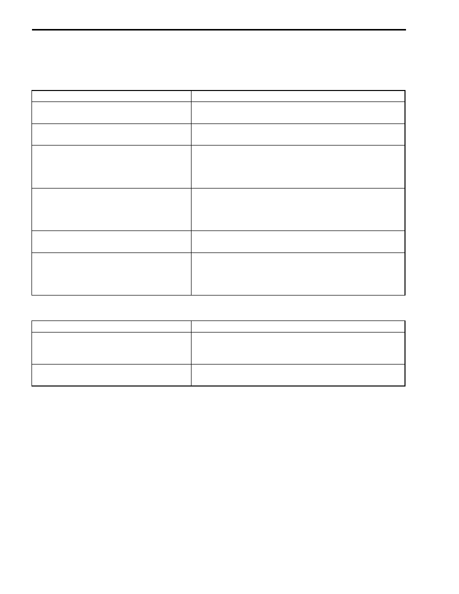
COMPENSATION OF INJECTION TIME (VOLUME)
The following different signals are output from the respective sensors for compensation of the fuel injection
time (volume).
INJECTION STOP CONTROL
SIGNAL
DESCRIPTION
ENGINE COOLANT TEMPERATURE SEN-
SOR SIGNAL
When engine coolant temperature is low, injection time (vol-
ume) is increased.
INTAKE AIR TEMPERATURE SENSOR
SIGNAL
When intake air temperature is low, injection time (volume)
is increased.
HEATED OXYGEN SENSOR SIGNAL
(E-02, 19, 54)
Air/fuel ratio is compensated to the theoretical ratio from
density of oxygen in exhaust gasses.The compensation
occurs in such way more fuel is supplied if detected air/fuel
ratio is lean and less fuel is supplied if it is rich.
BATTERY VOLTAGE SIGNAL
ECM operates on the battery voltage and at the same time,
it monitors the voltage signal for compensation of the fuel
injection time (volume). A longer injection time is needed to
adjust injection volume in the case of low voltage.
STARTING SIGNAL
When starting engine, additional fuel is injected during
cranking engine.
ACCELERATION SIGNAL/
DECELETATION SIGNAL
During acceleration, the fuel injection time (volume) is
increased in accordance with the throttle opening speed and
engine rpm. During deceleration, the fuel injection time (vol-
ume) is decreased.
SIGNAL
DESCRIPTION
TIP OVER SENSOR SIGNAL
(FUEL SHUT-OFF)
When the motorcycle tips over, the tip over sensor sends a
signal to the ECM. Then, this signal cuts OFF current sup-
plied to the fuel pump, fuel injector and ignition coil.
OVER-REV. LIMITER SIGNAL
The fuel injectors stop operation when engine rpm reaches
rev. limit rpm.