Volkswagen Golf / Golf GTI / Golf Variant. Service manual - part 881
♦ Torque Wrench 1332 40-200Nm - VAG1332-
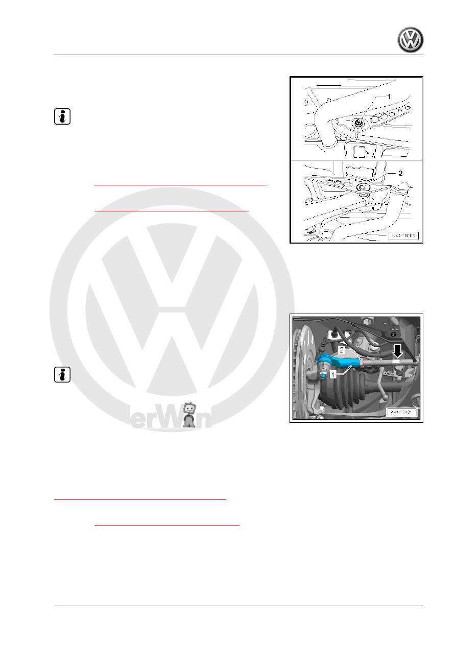
– Loosen nut -1-.
– Turn the eccentric bolt -2- until the specified value is reached.
Note
The maximum adjustment range is 90° to left or right of center
position.
– Tighten the nut -1-.
– After the nut -A- is tightened, check the toe value once more.
⇒ “3.4 Axle Alignment Specified Values”, page 298
Tightening Specifications
♦ Refer to
⇒ “5.1 Overview - Transverse Link”, page 181
3.11
Front Axle Toe, Adjusting
Special tools and workshop equipment required
♦ Torque Wrench 1332 40-200Nm - VAG1332-
♦ Torque Wrench 1332 Insert - Open Ring Wrench - 24mm -
VAG1332/9-
– To loosen or tighten the lock nut -2-, counterhold at the tie rod
end -1- with a suitable tool.
– Loosen the lock nut -2-.
– Adjust toe on left and right–hand wheels at hex -arrow-.
Note
♦
Make sure that boot on steering gear is not damaged or twis‐
ted. Twisted boots wear out quickly.
♦
Only tighten the lock nuts when the vehicle is resting on the
ground - the tie rod end must be parallel to the suspension
strut steering lever.
– Tighten the lock nut -2- and check the toe-in value again.
After tightening the lock nut -2-, it is possible that the value devi‐
ates slightly.
If the measured toe nevertheless lies within the tolerance, the
adjustment is correct. Refer to
⇒ “3.4 Axle Alignment Specified Values”, page 298
.
Tightening Specifications
♦ Refer to
⇒ “3.6 Steering Gear, Servicing”, page 363
3.12
Wheel Run-Out Compensation
A correct toe-in adjustment will not be possible without performing
lateral run-out compensation!
The lateral run–out of the wheel must be compensated for. Oth‐
erwise, measurement will result in false readings.