Volkswagen Golf / Golf GTI / Golf Variant. Service manual - part 880
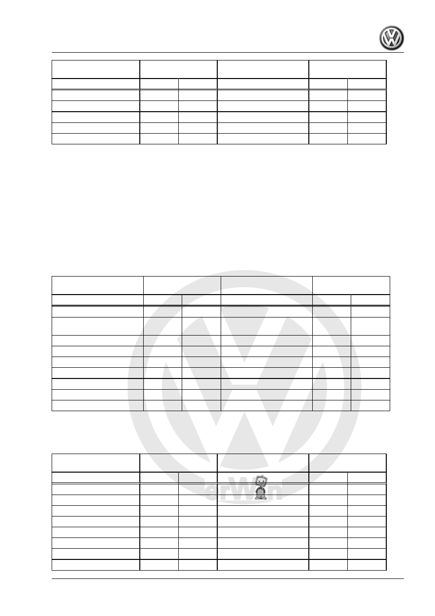
Components Of Front Axle
Removed And Installed
Wheel Alignment
Check Required
Components Of Rear Axle
Removed And Installed
Wheel Alignment
Check Required
Yes
No
Yes
No
Tie rod/tie rod end
X
Axle Beam
X
Steering Gear
X
Subframe
)
Suspension Strut
X
Stabilizer Bar
)
11) Requirement: Subframe and brackets were secured before removal.
3.6.2
Evaluating Need for Axle Alignment,
Multi-Link Suspension
When Vehicle Alignment is Necessary
♦ Vehicle shows handling problems.
♦ There is an accident damage and components were replaced.
♦ Axle components have been removed or replaced.
♦ Tire wear patterns are uneven.
Components Replaced
Front Axle Component Re‐
placed
Wheel Alignment
Check Required
Rear Axle Component Re‐
placed
Wheel Alignment
Check Required
Yes
No
Yes
No
Lower Control Arm
X
Lower transverse link
X
Bonded rubber bushings
for control arm
X
Upper Transverse Link
X
Wheel bearing housing
X
Tie rod
X
Tie rod/tie rod end
X
Wheel bearing housing
X
Steering Gear
X
Subframe
X
Subframe
X
Coil Spring
X
Suspension Strut
X
Shock Absorber
X
Stabilizer Bar
X
Stabilizer Bar
X
Trailing Arm
X
12) Requirement: Subframe and brackets were secured before removal.
Components Removed and Installed
Components Of Front Axle
Removed And Installed
Wheel Alignment
Check Required
Components Of Rear Axle
Removed And Installed
Wheel Alignment
Check Required
Yes
No
Yes
No
Lower Control Arm
)
Lower transverse link
X
Wheel bearing housing
X
Upper Transverse Link
X
Tie rod/tie rod end
X
Tie rod
X
Steering Gear
X
Wheel bearing housing
X
Subframe
)
Subframe
X
Suspension Strut
X
Coil Spring
X
Stabilizer Bar
)
Shock Absorber
X
Stabilizer Bar
X