Volkswagen Golf / Golf GTI / Golf Variant. Service manual - part 879
Front Axle
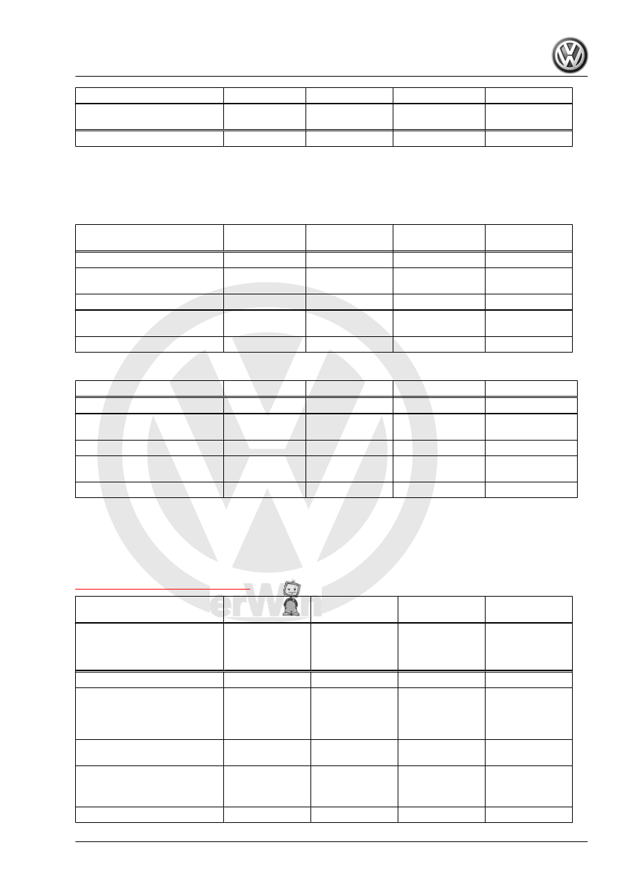
GTI
GTI Heavy Duty
PR numbers
G05, G06+2UC
G09, G06+2UJ
G06, G06+2UN
Standing height
368 ± 10 mm
383 ± 10 mm
5) Camber corrections are not possible. It can only be slightly corrected by push‐
ing the subframe.
6) The toe angle difference can also be indicated negatively in alignment com‐
puter, depending on manufacturer.
Rear Axle
Basic Suspen‐
sion
Sport Suspen‐
sion
Raised Suspen‐
sion
DCC Suspension
Camber
-1° 20′ ± 30′
-1° 20′ ± 30′
-1° 20′ ± 30′
-1° 20′ ± 30′
Maximum permissible differ‐
ence between both sides
maximum 30'
maximum 30'
maximum 30'
maximum 30'
Total toe (at specified camber)
10′ ± 10′
10′ ± 10′
10′ ± 10′
10′ ± 10′
Maximum permissible devia‐
tion from direction of rotation
maximum 20′
maximum 20′
maximum 20′
maximum 20′
Standing height
385 ± 10 mm
370 ± 10 mm
400 ± 10 mm
375 ± 10 mm
Rear Axle
GTI
GTI Heavy Duty
Camber
-1° 45′ ± 30′
-1° 20′ ± 30′
Maximum permissible differ‐
ence between both sides
maximum 30'
maximum 30'
Total toe (at specified camber)
16′ ± 10′
10′ ± 10′
Maximum permissible devia‐
tion from direction of rotation
maximum 20′
maximum 20′
Standing height
370 ± 10 mm
385 ± 10 mm
3.4.4
Axle Alignment Specified Values, Multi-Link Suspension, Golf Wagon
Specified values valid for all engine versions.
PR number explanations. Refer to
⇒ “3.7 Vehicle Data Label”, page 306
Front Axle
Basic Suspen‐
sion
Sport Suspen‐
sion
Raised Suspen‐
sion
DCC Suspension
PR numbers
G07, G01+0N4
+2UA,
G15, G07+0N4
+2UA
G08, G01+0N4
+2UA
G11, G01+0N4
+2UF,
G17, G07+0N4
+2UF
G04, G03+2UH
Total toe (wheels not pressed)
10′ ± 10′
10′ ± 10′
10′ ± 10′
10′ ± 10′
Camber (wheels in straight-
.
-30′ ± 30′
-41′ ± 30′
-16′ ± 30′
-36′ ± 30′
Maximum permissible differ‐
ence between both sides
maximum 30'
maximum 30'
maximum 30'
maximum 30'
Toe differential angle at 20°
steering angle. Refer to
1° 19′ ± 20′
1° 30′ ± 20′
1° 09′ ± 20′
1° 26′ ± 20′
Caster
7° 23′ ± 30′
7° 38′ ± 30′
7° 09′ ± 30′
7° 33′ ± 30′
Maximum permissible differ‐
ence between both sides
maximum 30'
maximum 30'
maximum 30'
maximum 30'
Standing height
383 ± 10 mm
368 ± 10 mm
398 ± 10 mm
373 ± 10 mm