Volkswagen Golf / Golf GTI / Golf Variant. Service manual - part 649


  Index      Volkswagen     Volkswagen Golf / Golf GTI / Golf Variant - service and repair manual 2013 year


Search            copyright infringement  


Content   ..  647  648  649  650   ..


Volkswagen Golf / Golf GTI / Golf Variant. Service manual - part 649


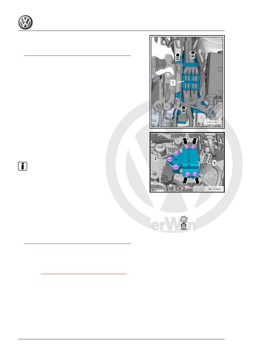
– Unclip the wiring guide -1- upward and move it slightly to the

side in direction of -arrows-.

– Support the engine in its installed position. Refer to

⇒ “2.5 Engine, Supporting in Installed Position”, page 33

 .

– Remove the bolts -2-, then the bolts -arrows- and remove the

transmission mount -1-.

Installing
Install in reverse order of removal. Note the following:

Note

Replace the bolts which have been tightened to torque.

The transmission support and the transmission mount support

arm must be absolutely parallel to each other before installing

bolts. Push the transmission up using a floor jack if necessary.

– Secure the transmission support to the longitudinal member.
– Pull the transmission up using the spindle on the engine sup‐

port bridge until the transmission support touches the trans‐

mission mount support arm.

– Install bolts by hand pay attention while doing so that the bolts

are not installed crooked.

– Check the adjustment of the assembly mounts. Refer to

⇒ “2.7 Subframe Mount, Checking Adjustment”, page 37

 .

– When the bolts are tightened to the tightening specification,

remove the Engine Support Bridge - 10-222A- from the en‐

gine.

Tightening Specifications
♦ Refer to 

⇒ “2.1 Overview - Subframe Mount”, page 29

♦ Refer to ⇒  Electrical Equipment; Rep. Gr.  27 ; Battery; Over‐

view - Battery .

2.4

Pendulum Support, Removing and In‐

stalling

Removing

Caution

This procedure contains mandatory replaceable parts. Refer

to component overview prior to starting procedure.

Mandatory Replacement Parts
♦ Bolts - Pendulum Support
– Remove the noise insulation. Refer to ⇒  Body Exterior; Rep.

Gr.  66 ; Noise Insulation; Overview - Noise Insulation .

– Remove the bolts -1, 2 and 3- and remove pendulum support.
Installing
Install in reverse order of removal. Note the following:
Tightening Specifications

Step

Bolts

Tightening Specification/Additional Turn

1.

-2 and 3-

50 Nm

2.

-1-

130 Nm

3.

-1 to 3-

Turn an additional 90°

♦ Refer to ⇒  Body Exterior; Rep. Gr.  66 ; Noise Insulation;

Overview - Noise Insulation .

2.5

Engine, Supporting in Installed Position

Special tools and workshop equipment required
♦ Engine Support Bridge - 10-222A-
♦ Engine Support Bridge - Engine Support 18 - 10-222A/18-
♦ Engine Support Bridge - Engine Support 29 - 10-222A/29-
♦ Engine Support - Basic Set Square Pipe - T40091/1- and En‐

gine Support - Movable Joint - T40091/3- from the Engine

Support - Basic Set - T40091-

♦ Engine Support Brackets - T40093/3- and Engine Support

Brackets - T40091/3-6- from the Engine Support - Supplement

Kit - T40093A-

♦ Engine Support Bridge - Special Hook (2 pc.) - 10-222A/20-
♦ Engine/Gearbox Support Shackle (2 pc.) - 10-222A/12-

Tool Development
– If the adapter for Engine Support Bridge - Engine Support 4 -

10-222A/4- does not have the indicated holes -arrow- shown

they must be added.

• Dimension -a- = 225 mm.
• Hole diameter = 12.5 mm
– Remove the engine cover. Refer to

⇒ “3.1 Engine Cover, Removing and Installing”, page 38

 .

– Unlock the retaining tab in direction of -arrow-, remove the left

engine cover mount -1-.

– Unclip the right mount -1- for the engine cover from the bracket

-2-.

– Place the Engine Support Bridge - Engine Support 29 -

10-222A/29- on both sides of the vehicle between the fender

bolting edge and the fender bolting plate underneath.

♦ Installed position:
“L” = -1- Adapter is Installed on the “Right” Side of the Vehicle

( Adapter Lock in the Opening on the Fender)

“R” (Not Illustrated), Adapter is Installed on the “Left” Side of the

Vehicle.
The arrow -2- always points in direction of travel.

– Push the Engine Support Bridge - Engine Support 18 -

10-222A/18- and two Engine Support - Movable Joint -

T40091/3- on the Engine Support Bridge - 10-222A- .

– Tighten the Engine Support Bridge - 10-222A- on the Engine

Support Bridge - Engine Support 29 - 10-222A/29- .

– Remove the windshield washer system washer fluid reservoir

filler tube. Refer to ⇒  Electrical Equipment; Rep. Gr.  92 ;

Windshield Washer System; Washer Fluid Reservoir, Remov‐

ing and Installing .

– If equipped remove the wire from the front area of the base of

the longitudinal member -arrow-. Do not disconnect the wiring

harness.

– Place the Engine Support Brackets - T40093/3-6- on both

sides of the longitudinal member the right longitudinal member

is shown here).

– If necessary carefully unclip the Air Conditioning (A/C) system

pipe in the front area. Do not disconnect the wiring harness.

Refer to ⇒  Heating, Ventilation and Air Conditioning; Rep. Gr. 

87 ; Refrigerant Circuit; System Overview - Refrigerant Cir‐

cuit .

• Lock the Engine Support Brackets - T40093/3-6- with the pin

-A- behind the edge of the longitudinal member -arrow-.

– Install the Engine Support Bracket - T40093/3- .
– Connect the Engine Support Brackets - T40093/3- over the

Engine Support - Basic Set - Square Pipe - T40091/1- with the

Engine Support Bridge - 10-222A- and tension.

– Engage the Brackets in the engine lifting eye over the Engine

Support Bridge - Special Hook (2 pc.) - 10-222A/20- and if

necessary over the Engine/Gearbox Support Shackle (2 pc.)

- 10-222A/12- .

– Lightly tension the engine/transmission assembly and Extrac‐

tor via the Brackets .


Content   ..  647  648  649  650   ..