Volkswagen Golf / Golf GTI / Golf Variant. Service manual - part 647


  Index      Volkswagen     Volkswagen Golf / Golf GTI / Golf Variant - service and repair manual 2013 year


Search            copyright infringement  


Content   ..  645  646  647  648   ..


Volkswagen Golf / Golf GTI / Golf Variant. Service manual - part 647


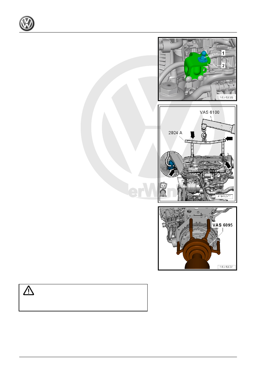
– Unclip the right engine cover mount -1-.

– Hook the Engine Sling - 2024A- to the engine and to the Shop

Crane - VAS6100- .

– To be aligned to the center of gravity of the engine assembly,

the hole rails must be inserted as shown in the illustration.

– Secure the mounting hooks and pins on the engine support

bridge using securing pins -arrows-.

– Lower the engine from the Engine and Gearbox Jack -

VAS6931- using the Shop Crane - VAS6100- .

– Remove the transmission alignment sleeve and secure the

transmission side of the engine on the Engine And Transmis‐

sion Holder - VAS6095- .

1.4

Engine, Installing

Caution

This procedure contains mandatory replaceable parts. Refer

to component overview prior to starting procedure.

Mandatory Replacement Parts
♦ Bolts - Transmission Mount
♦ Bolts - Engine to Transmission

Tightening Specifications

Note

The tightening specifications apply only to lightly greased,

oiled, phosphated or blackened nuts and bolts.

Additional lubricants, such as engine or transmission oil are

permissible, although lubricants containing graphite are not.

Do not use any ungreased parts.

Tightening specification tolerance: ±15%.

Component

Nm

Bolts and nuts

M6

10


M7

15


M8

20


M10

40


M12

65

♦ Refer to 

⇒ “2.1 Overview - Subframe Mount”, page 29

 .

♦ Securing engine to transmission. Refer to ⇒  Rep. Gr.  34 ;

Transmission, Removing and Installing; Transmission Tight‐

ening Specifications .

Procedure

Note

Replace the bolts that were tightened with an additional turn.

Replace the self-locking nuts and bolts, sealing rings, seals

and O-rings.

The hose connections as well as the air guide pipes and hoses

must be free of oil and grease before installing.

Secure hose connections with standard production clamps.

Refer to the Parts Catalog.

During installation, all cable ties must be installed at the same

location.

– Install intermediate plate. Refer to

⇒ Fig. ““Installing Intermediate Plate”“ , page 58

 .

Note

The illustration shows a vehicle with DSG

®

 transmission.

– If the alignment sleeves -A- for centering the engine and trans‐

mission are missing inside the cylinder block, then install the

sleeves.

Vehicles with a Manual Transmission
– If a needle bearing is installed in the crankshaft, remove the

needle bearing. Refer to

⇒ “3.4 Crankshaft Needle Bearing, Replacing”, page 65

 .

– If the clutch release bearing is worn, replace it. Refer to ⇒ 

Manual Transmission; Rep. Gr.  30 ; Clutch Mechanism;

Clutch Release Mechanism, Servicing .

– Lightly lubricate the transmission input shaft splines. Refer to

the Parts Catalog.

– Check the clutch plate alignment.
Vehicles with DSG

®

 Transmission

– If no needle bearing is installed in crankshaft, install needle

bearing. Refer to ⇒  Engine Mechanical, Fuel Injection and

Ignition; Rep. Gr.  13 ; Crankshaft; Crankshaft Needle Bearing,

Replacing .

Continuation for All Vehicles
– Attach transmission to engine.
– Install the starter. Refer to ⇒  Electrical Equipment; Rep. Gr. 

27 ; Starter; Starter, Removing and Installing .

– Guide the engine/transmission assembly into the body.

– Install the bolts -arrows- for the engine mount by hand all the

way.

– Install the bolts -arrows- for the transmission mount by hand

until it is in position.

Note

Only tighten the bolts to the specification when installing the sub‐

frame mount. Refer to

⇒ “2.1 Overview - Subframe Mount”, page 29

 .

– Remove the Engine/Gearbox Jack - Engine Support -

T10359A- from the engine.

– Install drive axles. Refer to ⇒  Suspension, Wheels, Steering;

Rep. Gr.  40 ; Drive Axle; Drive Axle, Removing and Installing .

Vehicles with a Manual Transmission
– Install the clutch slave cylinder. Refer to ⇒  Controls, Housing;

Rep. Gr.  34 ; Selector Mechanism; Selector Mechanism, Re‐

moving and Installing .

– Install the cables with the cable bracket. Refer to ⇒  Manual

Transmission; Rep. Gr.  30 ; Clutch Mechanism; Component

Location Overview - Clutch Mechanism .

Vehicles with DSG

®

 Transmission

– Install and adjust the selector lever cable. Refer to ⇒  Rep. Gr. 

34 ; Selector Mechanism; Overview - Selector Mechanism .

Continuation for All Vehicles
– Install the Air Conditioning (A/C) compressor. Refer to ⇒ 

Heating, Ventilation and Air Conditioning; Rep. Gr.  87 ; A/C

Compressor; Overview - A/C Compressor Power Unit .

– Install the ribbed belt. Refer to

⇒ “1.2 Ribbed Belt, Removing and Installing”, page 46

 .

– Adjust the subframe mount. Refer to

⇒ “2.6 Subframe Mount, Adjusting”, page 36

 .

– Install the battery tray. Refer to ⇒  Electrical Equipment; Rep.

Gr.  27 ; Battery; Overview - Battery .

– For the electrical connections and wiring routing. Refer to ⇒ 

Electrical Equipment; Rep. Gr.  97 ; Relay Carriers, Fuse Pan‐

els and E-Boxes; Component Location Overview - Relay Car‐

riers, Fuse Panels and E-Boxes and ⇒ Wiring diagrams,

Troubleshooting & Component locations.

– Install the air filter housing. Refer to

⇒ “3.2 Air Filter Housing, Removing and Installing”,

page 294

 .

– Install the engine cover. Refer to

⇒ “3.1 Engine Cover, Removing and Installing”, page 38

 .

– Check the oil level.
– Attach the coolant hoses to the heater core. Refer to

⇒ Fig. ““Connect the Coolant Hose to the Coupling”“ ,

page 245

 .

– Fill with coolant. Refer to 

⇒ page 218

 .

Note

Do not reuse used coolant.


Content   ..  645  646  647  648   ..