Volkswagen Golf / Golf GTI / Golf Variant. Service manual - part 650


  Index      Volkswagen     Volkswagen Golf / Golf GTI / Golf Variant - service and repair manual 2013 year


Search            copyright infringement  


Content   ..  648  649  650  651   ..


Volkswagen Golf / Golf GTI / Golf Variant. Service manual - part 650


2.6

Subframe Mount, Adjusting

Caution

This procedure contains mandatory replaceable parts. Refer

to component overview prior to starting procedure.

Mandatory Replacement Parts
♦ Bolts - Engine Mount
Procedure
– Remove the battery tray. Refer to ⇒  Electrical Equipment;

Rep. Gr.  27 ; Battery; Battery Tray, Removing and Installing .

– Support the engine in its installed position. Refer to

⇒ “2.5 Engine, Supporting in Installed Position”, page 33

 .

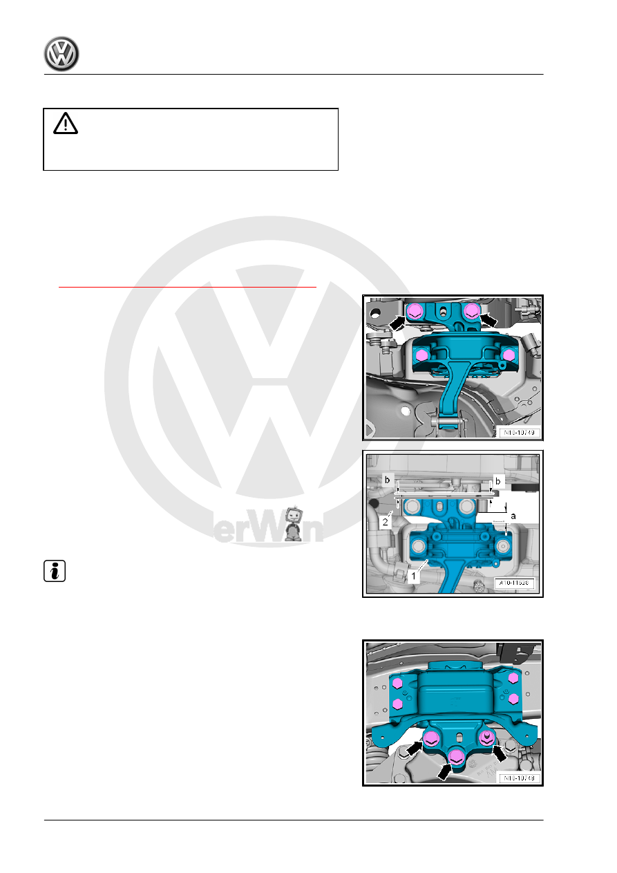
– Remove and replace the bolts -arrows- for the engine mount

one after the other (if this was not already done when the en‐

gine was installed).

– Install the bolts loosely.

– Slide engine/transmission assembly with a pry bar, until the

following dimensions are set:

• The clearance between the engine support -2- and the engine

mount -1- must be -a- = 10 mm.

• The casting edge on the engine support must be parallel to the

support arm.

• Dimension -b- = Dimension -b-.

Note

Distance -a- can also be checked using a suitable round stock.

– Tighten the bolts on the engine mount.

– Remove the replace the bolts -arrows- for the transmission

mount one after the other on the (if this was not already done

when the engine was installed).

– Install the bolts loosely.

– Pay attention that on the transmission side the support arm

and the transmission mount remain parallel.

• Dimension -x- = dimension -x-.
– Tighten the transmission support bolts.
Tightening Specifications
♦ Refer to 

⇒ “2.1 Overview - Subframe Mount”, page 29

 .

♦ Refer to ⇒  Electrical Equipment; Rep. Gr.  27 ; Battery; Over‐

view - Battery .

2.7

Subframe Mount, Checking Adjustment

Procedure
The following dimensions must be attained:
• The clearance between the engine support -2- and the engine

mount -1- must be -a- = 10 mm.

• The casting edge on the engine support must be parallel to the

support arm

• Dimension -b- = Dimension -b-.

Note

Distance -a- can also be checked using a suitable round stock.

– The distance measured is too small or too large, adjust the

subframe. Refer to

⇒ “2.6 Subframe Mount, Adjusting”, page 36

 .

3

Engine Cover

⇒ “3.1 Engine Cover, Removing and Installing”, page 38

 .

3.1

Engine Cover, Removing and Installing

Removing
– Carefully pull the engine cover off the bolts one after the other

in direction of -arrows-. Do not remove the engine cover on

one side or in a jerking manner.

Installing
– In order to prevent causing damage, do not hit the engine cov‐

er with your fist or tool.

– Position the engine cover while paying attention to the oil filler

tube and oil dipstick.

– Press the engine cover into the rubber grommets on the left

side first, then into the ones on the right side.

4

Special Tools

♦ Engine Sling - 2024A-
♦ Shop Crane - VAS6100-
♦ Engine And Transmission

Holder - VAS6095-


Content   ..  648  649  650  651   ..