Volkswagen Golf / Golf GTI / Golf Variant. Service manual - part 578


  Index      Volkswagen     Volkswagen Golf / Golf GTI / Golf Variant - service and repair manual 2013 year


Search            copyright infringement  


Content   ..  576  577  578  579   ..


Volkswagen Golf / Golf GTI / Golf Variant. Service manual - part 578


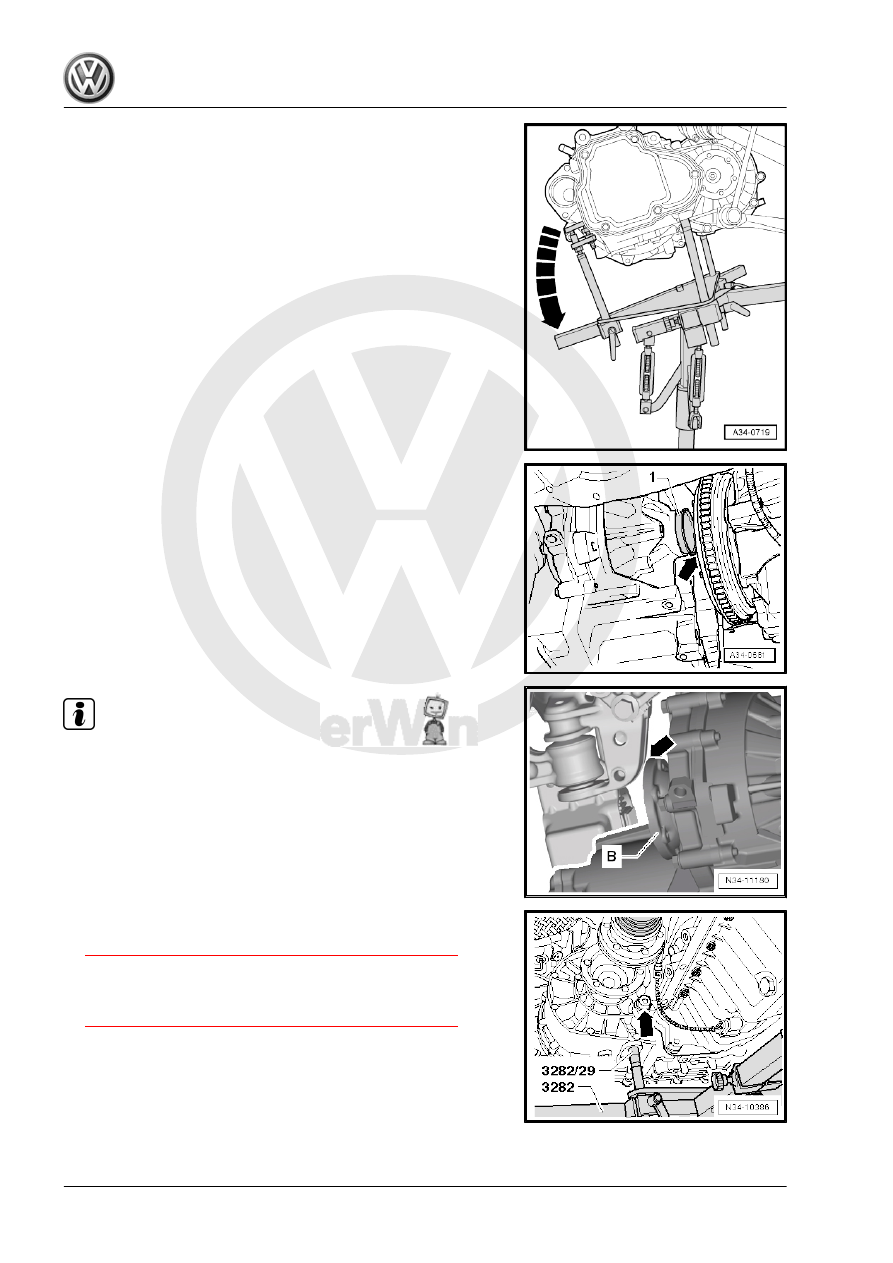
– Tip the transmission over the adjusting spindle for the Trans‐

mission Support - 3282- in the direction of -arrow-.

– Push the engine forward slightly with a second technician.

– Carefully lift the transmission with the Engine and Gearbox

Jack , while making sure that the seal -1- is guided through

without any damage to the pressure plate -arrow-.

Note

Guide the left flange shaft -B- past the subframe -arrow-.

– Align the transmission with the engine and install it.

– Install the bolt for the engine/transmission in the area of the

right flange shaft -arrow- (Refer to

⇒ “2.3 Transmission Tightening Specifications”, page 86

 .)

and tighten.

– Install lower engine/transmission connecting bolts and tighten.

Refer to

⇒ “2.3 Transmission Tightening Specifications”, page 86

 .

– After the transmission is attached to the engine, remove the

Engine and Gearbox Jack from the transmission.

– Reinsert the right flange shaft and tighten the bolt -arrow- to

the tightening specification. Refer to

⇒ “1.3 Right Seal, Replacing”, page 185

 .

– Install upper engine/transmission connecting bolts and tight‐

en. Refer to

⇒ “2.3 Transmission Tightening Specifications”, page 86

 .

– Attach the transmission bracket -A- with new hex collar bolts

-arrows- to the transmission and tighten. Refer to

⇒ “3.1 Overview - Subframe Mount”, page 87

 .

– Align the engine/transmission in its installed position. Lift until

the transmission bracket is touching the transmission mount

completely.

Caution

Risk of damaging threads in transmission bracket by inserting

bolts crooked.

♦ Before installing bolts -arrows-, transmission bracket and

transmission mount support arm must be absolutely par‐

allel to each other. If necessary, lift the back of the trans‐

mission using the Engine and Gearbox Jack .

Note

Install the engine/transmission mount free of tension. Refer to ⇒ 

Engine Mechanical, Fuel Injection and Ignition; Rep. Gr.  10 ;

Subframe Mount; Subframe Mount, Adjusting .

– Install new bolts -arrows- of left assembly mounting into trans‐

mission mount and tighten to tightening specification. Refer to

⇒ “3.1 Overview - Subframe Mount”, page 87

 .

Caution

Risk of accident!

• Only remove Engine Support Bridge - 10-222A- when all

subframe mount bolts are tightened to the tightening spec‐

ification.

– If equipped install the ground cable on the transmission mount

-arrow-.

– Install the pendulum support with new bolts -1 to 3-. Refer to

⇒  Engine Mechanical, Fuel Injection and Ignition; Rep. Gr. 

10 ; Subframe Mount; Pendulum Support, Removing and In‐

stalling .

– Assemble the exhaust system. Refer to ⇒  Rep. Gr.  26 ; Emis‐

sions Control; Overview - Emissions Control .

– Attach the drive axles to the transmission. Refer to ⇒  Sus‐

pension, Wheels, Steering; Rep. Gr.  40 ; Drive Axle; Drive

Axle, Removing and Installing .

– Attach the drive axle heat shield -arrows- (if equipped). Refer

to ⇒  Suspension, Wheels, Steering; Rep. Gr.  40 ; Drive Axle;

Drive Axle Heat Shield, Removing and Installing .

– If equipped, attach the Left Front Level Control System Sensor

- G78- on the lower control arm. Refer to ⇒  Suspension,

Wheels, Steering; Rep. Gr.  43 ; Level Control System Sensor;

Overview - Front Level Control System Sensor .

– Install the coupling rod -3- on both side of the stabilizer bar

-2-. Refer to ⇒  Engine Mechanical, Fuel Injection and Ignition;

Rep. Gr.  10 ; Subframe Mount; Overview - Subframe Mount .

– Connect the connector -1- to the Oil Level Thermal Sensor -

G266- .

– Transmission on vehicles with Start/Stop System: connect the

connector -arrow- to the Transmission Neutral Position Sensor

- G701- .

– Install the clutch slave cylinder and tighten the bolts

-B arrows-. Refer to

⇒ “1.4 Overview - Clutch Release Mechanism”, page 18

 .

– Install and secure the transmission support -A arrows-. Refer

to 

⇒ “3.1 Overview - Subframe Mount”, page 87

 .


Content   ..  576  577  578  579   ..