Volkswagen Golf / Golf GTI / Golf Variant. Service manual - part 576


  Index      Volkswagen     Volkswagen Golf / Golf GTI / Golf Variant - service and repair manual 2013 year


Search            copyright infringement  


Content   ..  574  575  576  577   ..


Volkswagen Golf / Golf GTI / Golf Variant. Service manual - part 576


– Remove all wires from the transmission.
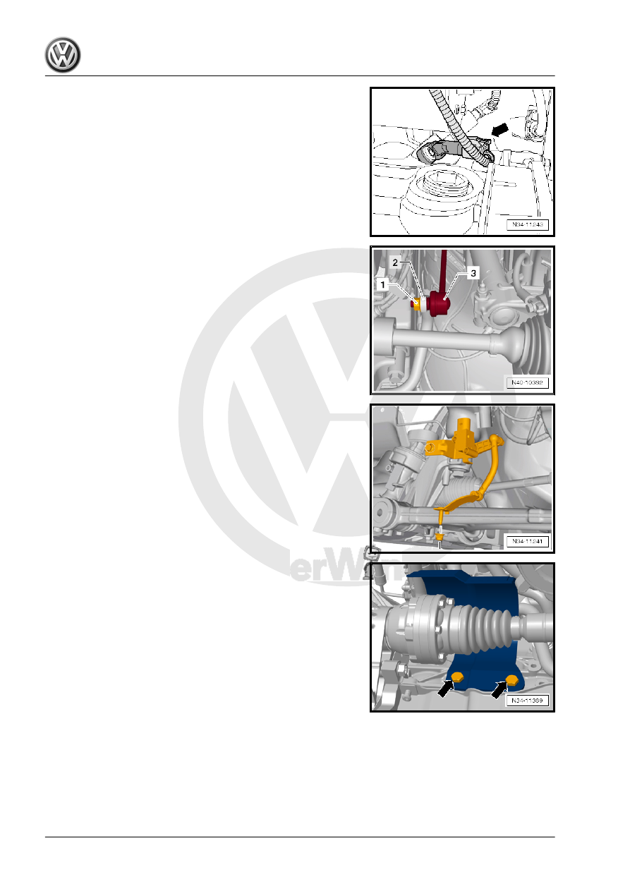
– Transmission on vehicles with Start/Stop System: disconnect

the connector -arrow- from the Transmission Neutral Position

Sensor - G701- .

– Remove the starter. Refer to ⇒  Electrical Equipment; Rep. Gr. 

27 ; Starter; Starter, Removing and Installing .

– Remove the nuts -1- from both sides of the coupling rod -3-.
– Remove the coupling rod -3- from both sides of the stabilizer

bar -2-.

– If equipped, remove the Left Front Level Control System Sen‐

sor - G78- from the lower control arm. Refer to ⇒  Suspension,

Wheels, Steering; Rep. Gr.  43 ; Level Control System Sensor;

Overview - Front Level Control System Sensor .

– Remove the drive axle heat shield -arrows- (if equipped). Re‐

fer to ⇒  Suspension, Wheels, Steering; Rep. Gr.  40 ; Drive

Axle; Drive Axle Heat Shield, Removing and Installing .

– Remove the drive axles from the flange shafts and tie them up

as high as possible. Be careful not to damage the surface pro‐

tection. Refer to ⇒  Suspension, Wheels, Steering; Rep. Gr. 

40 ; Drive Axle; Drive Axle, Removing and Installing .

– Install the two bolts into the flange and counterhold the flange

shaft with the pry lever to remove the right flange shaft bolt

-arrow-.

– Remove the flange shaft.

Note

Check the seal for leaks before removing the flange shaft. If

the seal has leaks, replace it when installing. Refer to

⇒ “1.3 Right Seal, Replacing”, page 185

 .

If transmission fluid leaks out while removing the flange shaft,

drain and refill transmission fluid on the installed transmission

and installed flange shaft. Refer to

⇒ “8 Transmission Fluid”, page 125

 .

– Attach the spindle -A- from the Seal Installer - Driver Set -

3066- into the threaded piece on the differential.

– Insert the Seal Installer - One-Piece Seal - T10148- and se‐

cure with the nut -B-.

Note

The Seal Installer - One-Piece Seal - T10148- protects the

right seal and the transmission from dirt.

A M8 x 105 mm bolt may be installed by hand into the differ‐

ential threaded piece instead of a spindle -A-.

Caution

There is a danger of causing damage to the decoupling ele‐

ment.

♦ Pay attention. Refer to ⇒  Rep. Gr.  26 ; Emissions Control;

Overview - Emissions Control .

– Remove the bracket bolts -arrows- for the exhaust system on

the subframe.

– Disconnect the exhaust system at the clamping sleeve

-arrow-. Refer to ⇒  Rep. Gr.  26 ; Exhaust Pipes/Mufflers;

Overview - Muffler .

– Remove bolts -1 through 3- and remove pendulum support.

– Loosen the hose clamps -arrows- and remove the left charge

air hose -A-. Refer to ⇒  Engine Mechanical, Fuel Injection and

Ignition; Rep. Gr.  21 ; Charge Air System; Overview - Charge

Air System .

– If present, remove nut -arrow- and ground cable.

– Remove the left assembly mounting hex bolts -arrows- from

the transmission mounting.

– Turn the spindles on the Engine Support Bridge - 10-222A-

and lower the transmission to dimension -a-.

• Dimension -a- = approximately 50 mm

– Remove the transmission bracket -A- -arrows-.

Align the Transmission Support - 3282- with the Transmission

Support - Mounting Plate 39 - 3282/39- in order to remove the

“0A4” transmission.
– Insert the Transmission Support - 3282- into the Engine and

Gearbox Jack - VAS6931- .

– Align the arms of the Transmission Support so that they match

up with the holes in the Adjustment Plate .

– Install the Mounting Elements -A and C-, on the Adjusting

Plate , as illustrated.

– Position the Engine-Transmission Jack under the vehicle. The

arrow symbol -B- on the Adjusting Plate points in the direction

of travel.


Content   ..  574  575  576  577   ..