Volkswagen Golf / Golf GTI / Golf Variant. Service manual - part 574


  Index      Volkswagen     Volkswagen Golf / Golf GTI / Golf Variant - service and repair manual 2013 year


Search            copyright infringement  


Content   ..  572  573  574  575   ..


Volkswagen Golf / Golf GTI / Golf Variant. Service manual - part 574


– Remove the boot and, if possible, the noise insulation from the

center console. Refer to

⇒ “1.4 Gearshift Knob, Removing and Installing”, page 54

 .

Secure the gearshift shaft as follows:
– Install the gearshift lever in neutral and, if necessary, press the

gearshift lever to the left and hold.

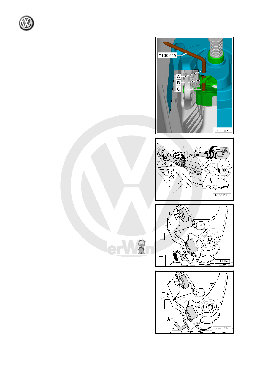
– Guide the Connecting Pin - T10027A- through the noise insu‐

lation -A-, hole -B- and into hole -C-.

– Position the safety mechanism on the cable retainer for the

shift cable and selector cable all the way to the right in direction

of -arrow-.

The spring will push the safety mechanism into the starting posi‐

tion.

– Push the angle -A- back in the starting position direction of

-arrow-.

• The bracket -A- must be pressed out of the selector housing

as far as the stop and it must face toward the rear.

– Remove the Locking Pin from the noise insulation -A- and the

holes -B and C-.

– Install the boot and if the insulation (if equipped). Refer to

⇒ “1.4 Gearshift Knob, Removing and Installing”, page 54

 .

– Make sure the gearshift shaft moves easily.
– Install the air filter housing if it was removed earlier. Refer to

⇒  Engine Mechanical, Fuel Injection and Ignition; Rep. Gr. 

24 ; Air Filter; Air Filter Housing, Removing and Installing .

1.7

Selector Mechanism, Checking

• The gearshift lever must rest in the 3rd/4th gear gate when the

transmission is in neutral.

– Operate the clutch.
– Move the gearshift lever (selector lever) several times through

all the gears. Make sure the reverse gear lock is working cor‐

rectly.

– It will be necessary to adjust the gearshift mechanism again if

a hook does not appear each time a gear is engaged. Refer

to 

⇒ “1.6 Selector Mechanism, Adjusting”, page 63

 .

1.8

Selector Shaft Seal, Replacing

Special tools and workshop equipment required
♦ Press Piece - Shift Rod/Alternator - VW423-
♦ Torque Wrench 1331 5-50Nm - VAG1331-
♦ Sealing Grease - G 052 128 A1-

Caution

This procedure contains mandatory replaceable parts. Refer

to component overview prior to starting procedure.

– Remove transmission shift lever and relay lever. Refer to

⇒ “1.3 Overview - Selector Mechanism”, page 53

 .

– Remove the seal with a screwdriver.

– Lightly oil new seal on outer circumference.
– Fill the space between the sealing and dust lip -arrow- halfway

with Sealing Grease - G 052 128 A1- .

– Drive in the seal using the Press Piece - Shift Rod/Alternator

- VW423- .

– Install the gearshift lever and relay lever. Refer to

⇒ “1.3 Overview - Selector Mechanism”, page 53

 .

2

Transmission, Removing and Instal‐

ling

⇒ “2.1 Transmission, Removing”, page 67
⇒ “2.2 Transmission, Installing”, page 77
⇒ “2.3 Transmission Tightening Specifications”, page 86

2.1

Transmission, Removing

Special tools and workshop equipment required
♦ Engine Support Bridge - 10-222A-
♦ Engine Support Bridge - Gearbox Adapter - 10-222A/29-
♦ Engine Support Bridge - Engine Support 18 - 10-222A/18-
♦ Engine/Gearbox Support Shackle (2 pc.) - 10-222A/12-
♦ Transmission Support - Pins 29 - 3282/29-
♦ Transmission Support - 3282-
♦ Transmission Support - Mounting Plate 39 - 3282/39-
♦ Transmission Support Elements (determine when mounting

the Adjustment Plate on the Transmission Support )

♦ Engine and Gearbox Jack - VAS6931-
♦ Torque Wrench 1331 5-50Nm - VAG1331-
♦ Torque Wrench 1332 40-200Nm - VAG1332-
♦ Transmission Support Jig - 3336- to transport the transmis‐

sion.

♦ Grease for Clutch Disc Shaft Splines - G 000 100-
♦ Allocate the grease for gearshift mechanism. Refer to the

Parts Catalog.

♦ Engine Support Bridge - Special Hook (2 pc.) - 10-222A/20-
♦ Spindle from the Seal Installer - Driver Set - 3066- or M8 x 105

bolt

♦ Seal Installer - One-Piece Seal - T10148-
♦ Engine Support - Basic Set Square Pipe - T40091/1- (quantity

2)

♦ Engine Support - Basic Set Movable Joint - T40091/3- (quan‐

tity 2)

♦ Engine Support - Supplement Kit Spindle - T40093/3- (quan‐

tity 2) from the Engine Support - Supplement Kit - T40093A-

♦ Engine Support Brackets - T40093/3-6- (quantity 2)

Caution

This procedure contains mandatory replaceable parts. Refer

to component overview prior to starting procedure.

Mandatory Replacement Parts
♦ Bolt - Transmission Support to Transmission
♦ Bolt - Transmission Support to Transmission Bracket
♦ Bolt - Pendulum Support to Transmission


Content   ..  572  573  574  575   ..