Volkswagen Golf / Golf GTI / Golf Variant. Service manual - part 302


  Index      Volkswagen     Volkswagen Golf / Golf GTI / Golf Variant - service and repair manual 2013 year


Search            copyright infringement  


Content   ..  300  301  302  303   ..


Volkswagen Golf / Golf GTI / Golf Variant. Service manual - part 302


– Install the side panel tail lamps. Refer to ⇒  Electrical Equip‐

ment; Rep. Gr.  94 ; Tail Lamps; Tail Lamp, Removing and

Installing .

– Additional step for GTI model. Refer to 

⇒ page 340

 .

Tightening Specifications
Adapter, Removing and Installing
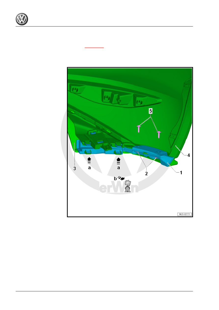
Removing
– Remove the screws -5-.
– Loosen the retainers in direction of -a arrows- and remove the

adapter -1- from the spoiler -3- and the bumper cover -4- in

direction of -arrow b-.

Installing
– Check the spring nuts -2-.
– Push the adapter -1- onto the bumper cover -4- and engage

with the spoiler -3-.

– Tighten the screws -5-.

Tightening Specifications

2.5.2

Bumper Cover, Removing and Instal‐

ling, Wagon

Note

Depending on the model version, slight deviations of the bumper

cover must be considered when removing and installing.

Special tools and workshop equipment required
♦ Torque Wrench 1783 - 2-10Nm - VAG1783-
Removing

– Remove the side panel tail lamps. Refer to ⇒  Electrical Equip‐

ment; Rep. Gr.  94 ; Tail Lamps; Tail Lamp, Removing and

Installing .

– Remove the screws -3- in the wheel housing (pointing upward)

on the left and right sides.

– Remove the screws -4- near the wheel housing liner on the

left and right sides.

– Remove the expanding rivets -5- from underneath.
A second technician is required for the rest of the removal pro‐

cedure.
– Pull the bumper cover -1- out of the left and right guide retain‐

ers -2- on the side panel in direction of -a arrows-.

– Loosen the bumper cover -1- upward from the retainers in di‐

rection of -b arrows-.

– Remove the bumper cover -1- in direction of -arrows c- parallel

from the vehicle with the help of a second technician.

– Disconnect the connectors of any electrical components (if

present).

For notes and procedures regarding the parking aid. Refer to ⇒ 

Electrical Equipment; Rep. Gr.  94 ; Parking Aid .
For notes and procedures regarding the parallel parking assis‐

tance. Refer to ⇒  Electrical Equipment; Rep. Gr.  94 ; Parallel

Parking Assist .
Installing

– Connect the connectors to any electric components (if

present).

– Guide the bumper cover -1- parallel to the vehicle in direction

of -a arrows-.

– Push the bumper cover -1- onto the left and right guides -2-

on the side panel until they engage with each other in direction

of -arrow b-.

– Pay attention to the parallel alignment and the gap dimen‐

sions. Refer to ⇒ Body Repair; Rep. Gr.  00 ; Body Gap

Dimensions; Rear Body .

– Install the expanding rivets -7- from underneath.
– Install the left and right wheel housing liner screws -6-.
– Install the left and right screws -5- in the wheel housing (facing

up).

– Install the side panel tail lamps. Refer to ⇒  Electrical Equip‐

ment; Rep. Gr.  94 ; Tail Lamps; Tail Lamp, Removing and

Installing .

Tightening Specifications

2.6

Impact Member, Removing and Installing

Removing


Content   ..  300  301  302  303   ..