Volkswagen Golf / Golf GTI / Golf Variant. Service manual - part 301
2.4
Overview - Guides
⇒ “2.4.1 Overview - Guides, Sedan”, page 336
⇒ “2.4.2 Overview - Guides, Wagon”, page 337
2.4.1
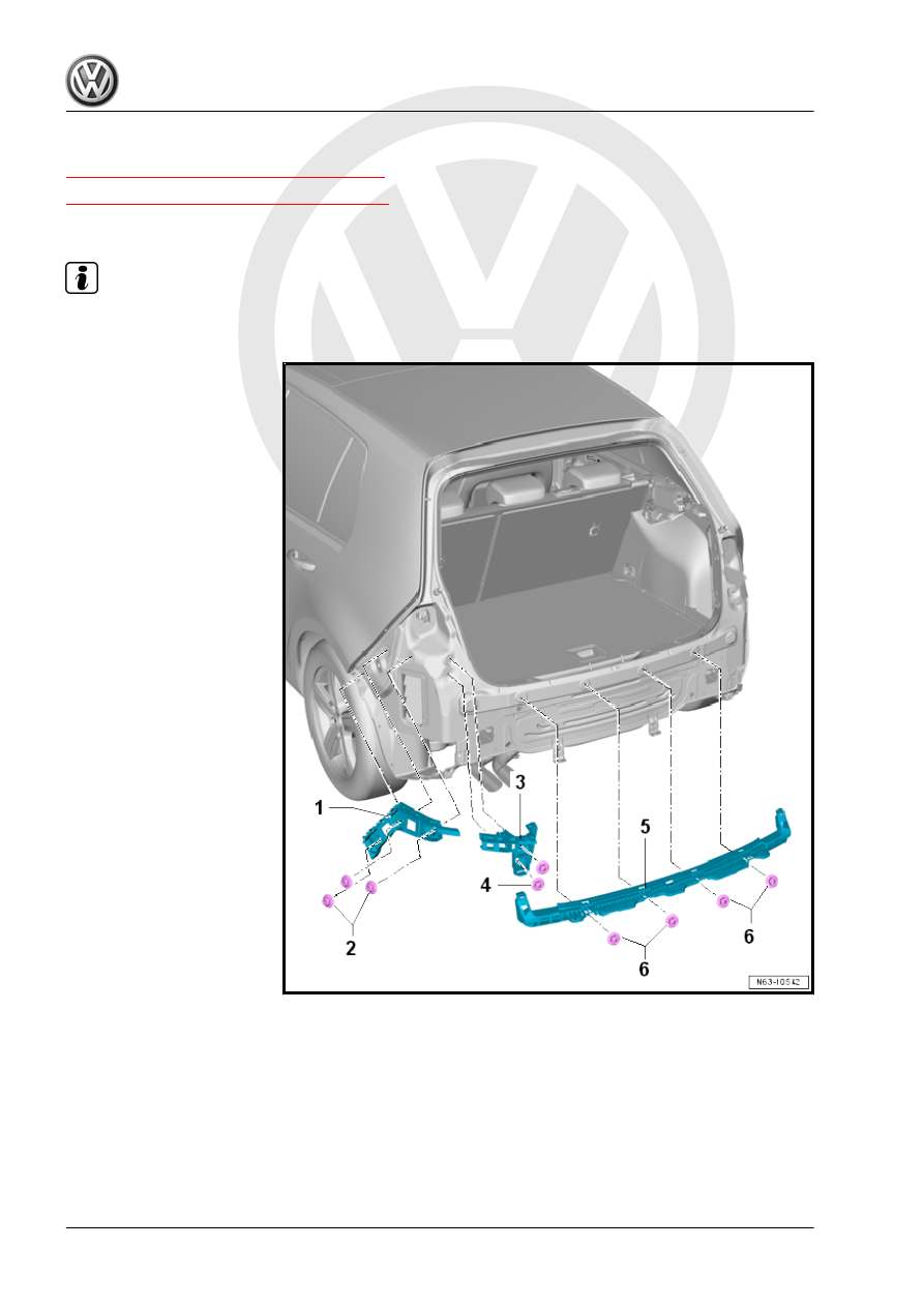
Overview - Guides, Sedan
Note
There are different versions. Refer to the Parts Catalog.
1 - Guide
❑ Right and left
2 - Hex Nut
❑ 3.5 Nm
❑ Quantity: 3 on each side
3 - Guide
❑ On the right and left
sides for the tail lamp
4 - Hex Nut
❑ 3.5 Nm
❑ Quantity: 2 on each side
5 - Center Guide
6 - Hex Nut
❑ 3.5 Nm
❑ Quantity: 4