Volkswagen Golf Variant / Jetta. Manual - part 113
 

  Index      Volkswagen     Volkswagen Golf Variant (2007), Jetta (2005) - service repair manual


Search            


Content   ..  111  112  113  114   ..


Volkswagen Golf Variant / Jetta. Manual - part 113


Connecting .

Filter Housing, Removing and Installing .

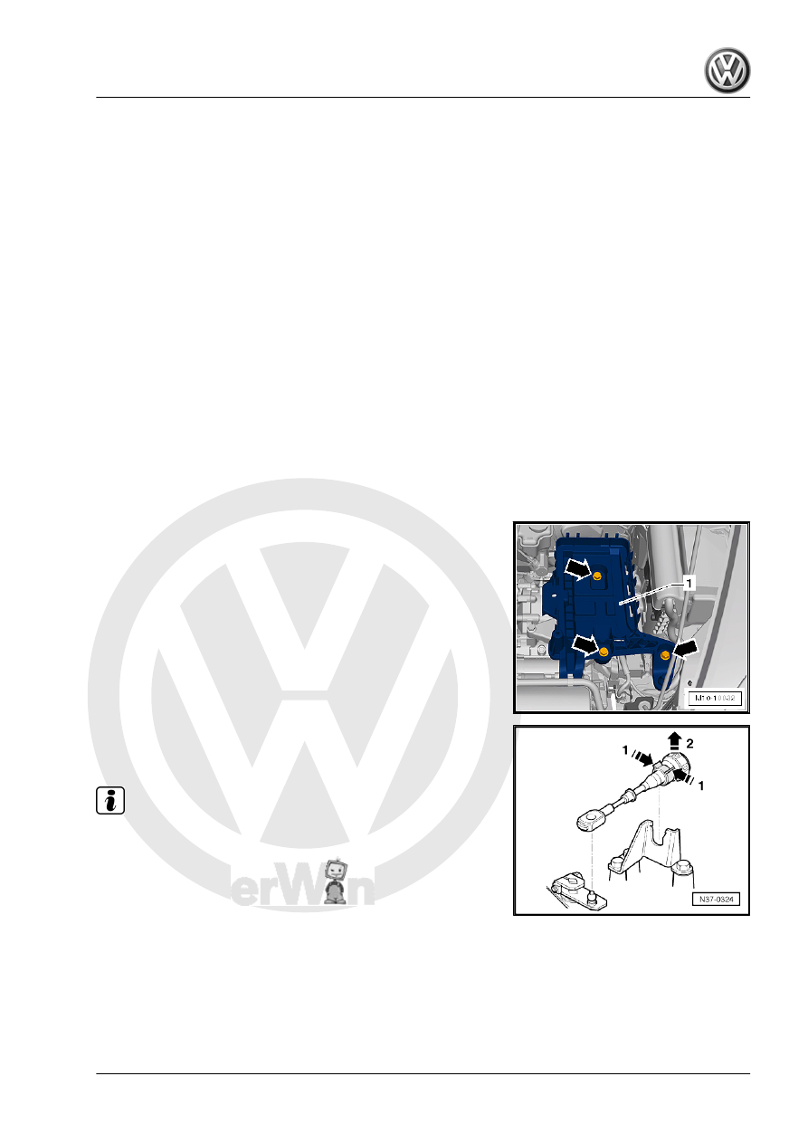
– Remove the battery and the battery tray. Refer to ⇒  Electrical

Equipment; Rep. Gr.  27 ; Battery; Battery, Removing and In‐

stalling .

– To remove the selector lever cable from the transmission, re‐

lease the selector lever cable -arrows 1- and then remove it

from the cable bracket -arrow 2-.

Note

♦

Do not use pliers because the mounting tabs on the cable

bracket could break off.

♦

Do not bend or kink the selector lever cable.

7. Transmission, Removing and Installing, Jetta from MY 2011    

83

using for example an open end wrench -2-.

– Mount the Hose Clamps - Up To 25mm - 3094- on the hoses

and remove the hoses form the ATF cooler.

– Disconnect the connections from the transmission and starter.
♦ Multifunction transmission range switch
♦ Starter
– Remove the upper starter bolt.
– Remove the upper bolts between the engine and the trans‐

mission.

– Remove the plenum chamber cover. Refer to ⇒  Body Exterior;

Rep. Gr.  50 ; Plenum Chamber Cover; Plenum Chamber

Cover, Removing and Installing .

– Remove the bolts -arrows- for the left and right lock carrier

retaining brackets.

– Remove the lower mounts on the Engine Support Bridge - En‐

gine Support 28 - 10-222A/28- and replace with the Engine

Support Bridge - Engine Support 28-2 - 10-222A/28-2- .

– Remove the bolts -arrows- for securing the engine support

bridge on the lock carrier from the Engine Support 28-2 -

10-222A/28-2- .

• Use the bolts in the Engine Support Bridge - Engine Support

28-2 - 10-222A/28-2- for attaching the Engine Support Bridge

- Engine Support 28 - 10-222A/28- . Not the bolts for the re‐

taining bracket.

84

10-222A/28- and tighten the bolts to 8 Nm -arrows-.

Caution

A second technician is needed to mount the Engine Support

Bridge - 10-222A- on the vehicle to prevent the Engine Support

Bridge - 10-222A- from tipping.

– If there are hose and cable connections located near the en‐

gine lifting eyes for the Engine Support Bridge - 10-222A- ,

these must now be removed.

– Install the Engine Support Bridge - 10-222A- as shown.
– First slide the Moveable Joints -2- onto the Square Pipe from

the Engine Support Bridge - 10-222A- .

– Mount the Engine Support Bridge - 10-222A- on the suspen‐

sion strut towers and have a second technician hold it to

prevent it from tipping.

– Push the Engine Support - Basic Set - Square Pipe -

T40091/1- -5- from the front left and right through the Engine

Support Bridge - Engine Support 28 - 10-222A/28- -6- and

place on each side of the Engine Support - Supplement Kit -

Movable Joint - T40093/4- -4-.

– Slide the Engine Support - Basic Set - Rail with Holes -

T40091/2- -8- with the Engine Support - Supplement Kit Mount

- T40093/5- -9- in the Engine Support - Supplement Kit -

Moveable Joint - T40093/4- -4-.

– Install the locking pins into the Engine Support - Basic Set -

Rail with Holes - T40091/2- -8- and secure it with the cotter

pins.

7. Transmission, Removing and Installing, Jetta from MY 2011    

85

gine Support 31 - Adapter 2 -

10-222A/31-2-
2 - Engine Support - Basic Set

- Moveable Joint - T40091/3-
3 - Engine Support Bridge - En‐

gine Support 31 - Adapter 1 -

10-222A/31-1-
4 - Engine Support - Supple‐

ment Kit - Movable Joint -

T40093/4-
5 - Engine Support - Basic Set

- Square Pipe - T40091/1-
6 - Engine Support Bridge - En‐

gine Support 28 - 10-222A/28-

with Engine Support Bridge -

Engine Support 28-2 -

10-222A/28-2-
7 - Engine/Gearbox Support

Shackle (2 pc.) - 10-222A/12-

❑ Engaged in the engine

lifting eye.

8 - Engine Support - Basic Set

- Rail with Holes - T40091/2-
9 - Engine Support - Supple‐

ment Kit - Mount 5 - T40093/5-
10 - Engine Support Bridge -

Spindle - 10-222A/11-

❑ Engaged in the Engine/

Gearbox Support

Shackle (2 pc.) -

10-222A/12- .

– Tighten all the threaded connections on the Engine Support

Bridge - 10-222A- hand-tight. While doing so, adjust the height

of the Engine Support Bridge - 10-222A- parallel over the En‐

gine Support Bridge - Engine Support 28 - 10-222A/28- .

– Lightly tension the engine/transmission assembly via the En‐

gine Support Bridge - 10-222A- spindle, do not lift.

– Remove the upper engine/transmission connecting bolts.

86


Content   ..  111  112  113  114   ..