Toyota Corolla (2004+). Manual - part 119

75-7
ENGINE HOOD/DOOR
- FRONT DOOR
750DD-02
OVERHAUL
HINT:
F
Installation is in the reverse order of the removal. But the installation is indicated only when it has a
point.
F
In the RH side, work in the same procedure as in the LH side.
1.
REMOVE FRONT ARMREST ASSY LH
Clip
(a) Using a screwdriver, remove the front armrest.
HINT:
Tape the screwdriver tip before use.
Clip
: Claw
B59502
2.
REMOVE POWER WINDOW REGULATOR MASTER
SWITCH ASSY (W/ POWER WINDOW)
Clip
(a) Using a screwdriver, remove the power window regulator
master switch assembly from the trim board.
HINT:
Tape the screwdriver tip before use.
(b) Disconnect the master switch connector.
(c)
Remove the 3 screws and base panel from the master
: Claw
B59503
switch.
w/o Power Door Lock
3.
REMOVE FRONT ARMREST BASE PANEL UPPER LH
(W/O POWER WINDOW)
(a) w/o Power door lock:
Remove the front armrest base panel upper.
(1)
Using a screwdriver, remove the front armrest base
panel upper from the trim board.
HINT:
Tape the screwdriver tip before use.
: Claw
B59504
(b) w/ Power door lock:
Remove the front armrest base panel upper.
(1)
Using a screwdriver, remove the front armrest base
panel upper from the trim board.
HINT:
Tape the screwdriver tip before use.
(2)
Disconnect the door lock switch connector.
(3)
Remove the door lock switch from the base panel.

75-8
ENGINE HOOD/DOOR
- FRONT DOOR
4.
REMOVE FRONT DOOR WINDOW REGULATOR
HANDLE ASSY (W/O POWER WINDOW)
(a) Using a shop rag, remove the snap ring.
(b) Remove the front door window regulator handle and
plate.
BO0020
5.
REMOVE FRONT DOOR LOWER FRAME BRACKET
Clip
GARNISH LH
(a) Remove the lower frame bracket garnish.
Claw
B58051
6.
REMOVE FRONT DOOR TRIM BOARD SUB-ASSY LH
Clip
(a) Remove the 3 screws.
(b) Using a screwdriver, disengage the clips and then pull the
trim board upward to remove it.
HINT:
Tape the screwdriver tip before use.
B59006
7.
REMOVE FRONT DOOR INSIDE HANDLE SUB-ASSY
LH
(a) Remove the inside handle, and then disconnect the 2
cables from the inside handle.
B58050
8.
REMOVE FRONT DOOR SERVICE HOLE COVER LH
(a) Disconnect each connector, and remove the front door service hole cover.
NOTICE:
Remove the remaining tape on the body side.

75-9
ENGINE HOOD/DOOR
- FRONT DOOR
w/o Front No. 2 Speaker Assy
9.
REMOVE OUTER REAR VIEW MIRROR ASSY LH
(a) Disconnect the outer mirror connector.
(b) w/o Front No. 2 speaker assembly:
Remove the outer mirror assembly.
(1)
Remove the 3 nuts and outer mirror.
(c)
w/ Front No. 2 speaker assembly:
Remove the outer mirror assembly.
(1)
Disconnect the speaker connector.
H19808
(2)
Remove the 2 nuts and front No. 2 speaker.
(3)
Remove the nut and outer mirror.
10. REMOVE FRONT DOOR BELT MOULDING ASSY LH
(See page 76-12)
11. REMOVE FRONT NO.1 SPEAKER ASSY
(a) Disconnect the speaker connector.
(b) Using a drill of less than ø 4 mm (0.16 in.), drill out the rivet
heads and remove the speaker.
(c)
Gently and vertically put the drill onto the rivet, and cut the
rivet flanges.
NOTICE:
F
Prizing the hole with a drill can lead to damage to the
H19810
rivet hole or breaking the drill.
F
Be careful with the cut rivet, because it is hot.
(d) Even if the flange is taken off, continue drilling and push
out the remaining fragments with the drill.
(e) Using a vacuum cleaner, remove the drilled rivet and dust
from the inside of the door.
12. REMOVE FRONT DOOR INSIDE PANEL PLATE LH
(a) Remove the 3 screws and front door inside panel plate.
B59014
13. REMOVE FRONT DOOR GLASS SUB-ASSY LH
HINT:
Insert a shop rag inside the door panel to prevent the glass from
being scratched.
(a) Open the door glass until the bolts appear in the service
hole.
(b) Remove the 2 bolts and door glass.
NOTICE:
B58052
Do not damage the door glass.

75-10
ENGINE HOOD/DOOR
- FRONT DOOR
HINT:
Pull the glass upward to remove it.
14. REMOVE FRONT DOOR GLASS RUN LH
(a) Remove the front door glass run.
15. REMOVE FRONT DOOR WINDOW REGULATOR SUB-ASSY LH (W/O POWER WINDOW)
(a) Loosen the 6 bolts.
NOTICE:
When the bolts are removed, the front door window regulator might drop and be deformed.
(b) Remove the 6 bolts and front door window regulator.
16. REMOVE FRONT DOOR WINDOW REGULATOR
SUB-ASSY LH (W/ POWER WINDOW)
(a) Disconnect the window regulator connector.
(b) Loosen the 6 bolts.
NOTICE:
When the bolts are removed, the front door window regula-
tor might drop and be deformed.
(c)
Remove the 6 bolts and front door window regulator.
B59019
17. REMOVE POWER WINDOW REGULATOR MOTOR ASSY LH (W/ POWER WINDOW)
(a) Place matchmarks on the window regulator motor bracket and regulator gear.
(b) Remove the 3 screws and motor.
18. REMOVE FRONT DOOR FRAME SUB-ASSY REAR
LOWER LH
(a) Remove the bolt and front door frame rear lower.
B59623
19. REMOVE FRONT DOOR OUTSIDE HANDLE COVER
LH
(a) Remove the hole plug.
(b) Using a torx wrench (T30), loosen the screw and remove
the door outside handle cover with the door lock key cylin-
der installed.
20. REMOVE FRONT DOOR LOCK ASSY LH (W/O
POWER DOOR LOCK)
B56825
(a) Using a torx wrench (T30), remove the 3 screws and the
door lock assembly.

75-11
ENGINE HOOD/DOOR
- FRONT DOOR
21. REMOVE FRONT DOOR W/MOTOR LOCK ASSY LH
(W/ POWER DOOR LOCK)
(a) Disconnect the power door lock connector.
(b) Using a torx wrench (T30), remove the 3 screws and the
power door lock assembly.
B59020
22. REMOVE FRONT DOOR HANDLE ASSY OUTSIDE LH
(a) Pushing the outside handle in the arrow mark direction in
the illustration, remove the outside handle.
B56613
23. REMOVE FRONT DOOR OUTSIDE HANDLE FRAME
SUB-ASSY LH
(a) Using a torx wrench (T30), loosen the screw.
Torque: 4.0 N·m (41 kgf·cm, 35 in.·lbf)
(b) Using pliers, disengage the clips and remove the door
outside handle frame, as shown in the illustration.
NOTICE:
Be sure to remove the outside handle together with the
B57102
clips, because the clips will be damaged if the clips remain
attached to the door panel.
24. REMOVE FRONT DOOR WEATHERSTRIP LH
(a) Remove the door panel side bolt and disconnect the front door check assembly.
(b) Using a screwdriver, remove the weatherstrip.
HINT:
Tape the screwdriver tip before use.
25. INSTALL FRONT DOOR WEATHERSTRIP LH
(a) Install the weatherstrip.
(b) Install the front door check assembly with the door panel side bolt.
Torque: 5.5 N·m (56 kgf·cm, 49 in.·lbf)
26. INSTALL FRONT DOOR OUTSIDE HANDLE FRAME SUB-ASSY LH
(a) Using a torx wrench (T30), install the outside handle.
Torque: 4.0 N·m (41 kgf·cm, 35 in.·lbf)
27. INSTALL FRONT DOOR LOCK ASSY LH (W/O POWER DOOR LOCK)
(a) Apply MP grease to the sliding and rotating parts of the door lock.
(b) Apply adhesive to the 3 screws.
Part No.08833-00070, THREE BOND 1324 or equivalent
(c)
Using a torx wrench (T30), install the door lock assembly with the 3 screws.
Torque: 5.0 N·m (51 kgf·cm, 44 in.·lbf)

75-12
ENGINE HOOD/DOOR
- FRONT DOOR
28. INSTALL FRONT DOOR W/MOTOR LOCK ASSY LH
(W/ POWER DOOR LOCK)
(a) Install a new door lock wire harness packing.
NOTICE:
F
If reusing the removed lock with front door motor, the
packing in the connecting part should be replaced
with a new one.
F
Be careful that no grease and dirt will stick to the
B59020
packing surface in the connecting part.
F
Reusing the removed packing or using a damaged
packing will cause water to penetrate through the
connecting part, and it will result in a malfunction of
the door lock.
(b) Insert the outside handle link into the lock assembly with
front door motor, and then set it to the door panel.
NOTICE:
Make sure that the outside handle link is securely engaged
with the lock assembly.
(c)
Apply MP grease to the sliding and rotating parts of the
door lock.
(d) Apply adhesive to the 3 screws.
Part No.08833-00070, THREE BOND 1324 or equiva-
lent.
(e) Using a torx wrench (T30), install the front door lock as-
sembly with the 3 screws.
Torque: 5.0 N·m (51 kgf·cm, 44 in.·lbf)
(f)
Connect the power door lock connector.
29. INSTALL FRONT DOOR OUTSIDE HANDLE COVER
LH
(a) Using a torx wrench (T30), install the door outside handle
cover with the screw.
Torque: 4.0 N·m (41 kgf·cm, 35 in.·lbf)
B56614
30. INSTALL FRONT DOOR FRAME SUB-ASSY REAR LOWER LH
(a) Install the front door frame rear lower with the bolt.
Torque: 6.2 N·m (63 kgf·cm, 55 in.·lbf)
31. INSTALL POWER WINDOW REGULATOR MOTOR ASSY LH (W/ POWER WINDOW)
(a) Align the matchmarks on the regulator motor bracket and regulator gear.
(b) Install the 3 screws.
Torque: 5.4 N·m (55 kgf·cm, 48 in.·lbf)
HINT:
Never rotate the motor to the down direction until the window glass installation has done.

75-13
ENGINE HOOD/DOOR
- FRONT DOOR
32. INSTALL FRONT DOOR WINDOW REGULATOR
SUB-ASSY LH (W/ POWER WINDOW)
(a) Apply MP grease to the sliding and rotating parts of the
window regulator.
NOTICE:
Do not apply grease to the spring of the window regulator.
(b) Apply the window regulator to the 6 regulator installation
holes on the front door panel, temporarily install the win-
B59024
dow regulator with the installation bolts.
(c)
Tighten the 6 bolts and the temporarily installed bolt.
Torque: 8.0 N·m (82 kgf·cm, 71 in.·lbf)
(d) Connect the window regulator connector.
33. INSTALL FRONT DOOR WINDOW REGULATOR
SUB-ASSY LH (W/O POWER WINDOW)
(a) Apply MP grease to the sliding and rotating parts of the
window regulator.
NOTICE:
Do not apply grease to the spring of the window regulator.
(b) Install the front door window regulator with the 6 bolts.
Torque: 8.0 N·m (82 kgf·cm, 71 in.·lbf)
B59025
34. INSTALL FRONT DOOR GLASS SUB-ASSY LH (W/
POWER WINDOW)
NOTICE:
Do not damage the door glass.
(a) Put the door glass in the door panel carefully.
(b) Install the door glass with the 2 bolts to the window regula-
tor.
Torque: 8.0 N·m (82 kgf·cm, 71 in.·lbf)
B58052
(c)
Inspect the power window operation.
HINT:
When the installation point of the front door glass does not
match, adjust the regulator position in the manual operation.
(1)
Connect the power window switch to the wire har-
ness and turn the ignition switch ON.
(2)
Repeat UP and DOWN operation several times in
the manual operation.
(3)
Check if AUTO UP AUTO DOWN operates in the
automatic operation.
HINT:
F
Note that the jam protection function does not operate
just after resetting.
F
Reset the regulator again when performing the reverse
operation after closing the window fully in the AUTO UP
operation.

75-14
ENGINE HOOD/DOOR
- FRONT DOOR
35. INSPECT POWER WINDOW FUNCTION (W/ POWER
WINDOW) (See page 70-2)
36. INSTALL FRONT NO.1 SPEAKER ASSY
(a) Install the front speaker to the door.
(b) Using an air riveter or hand riveter, install the front speak-
er.
H19811
NOTICE:
F
Do not prize a riveter, because the riveter will be
dam-
Riveter
aged, and the mandrel will be bent.
Mandrel
H02440
F
Do not tilt the riveter when removing the rivet, be-
cause the materials are not tightened firmly.
Riveter
Riveter
H02441
F
Install the rivet while attaching the materials, be-
cause they are not tightened firmly.
(c)
Connect the speaker connector.
Riveter
H02442

75-15
ENGINE HOOD/DOOR
- FRONT DOOR
w/o Front No. 2 Speaker Assy
37. INSTALL OUTER REAR VIEW MIRROR ASSY LH
(a) w/o Front No. 2 speaker assembly:
Install the outer mirror assembly.
(1)
Install the outer mirror with the 3 nuts.
Torque: 8.0 N·m (82 kgf·cm, 71 in.·lbf)
(b) w/ Front No. 2 speaker assembly:
Install the outer mirror assembly.
(1)
Temporarily install the outer mirror with the nut.
H19808
(2)
Temporarily install the front No. 2 speaker with the
2 nuts.
(3)
Tighten the 3 nuts.
Torque: 8.0 N·m (82 kgf·cm, 71 in.·lbf)
(4)
Connect the speaker connector.
(c)
Connect the outer mirror connector.
38. INSTALL FRONT DOOR SERVICE HOLE COVER LH
(a) Install a new service hole cover to the door panel.
HINT:
F
When installing the service hole cover, pull out the links
and connectors through the service hole cover.
F
There should be no wrinkles or folds after attaching the
service hole cover.
F
After attaching the service hole cover, sealing condition
Tape
B59796
should be confirmed.
39. INSTALL FRONT DOOR WINDOW REGULATOR
30
5_
HANDLE ASSY (W/O POWER WINDOW)
(a) Install the regulator handle with the snap ring.
Front
HINT:
With the door window fully closed, install the plate and regulator
handle with the snap ring as shown in the illustration.
Plate
B58054

75-1
ENGINE HOOD/DOOR
- HOOD
HOOD
750DB-02
ADJUSTMENT
HINT:
Since the centering bolt is used as a hood hinge and hood lock
set bolt, the hood and hood lock can not be adjusted with it on.
Substitute a bolt with washer for the centering bolt.
Centering Bolt
Standard Bolt
B50717
1.
INSPECT HOOD SUB-ASSY
(a) Check that the clearance is within the standard value.
A: 4.0 (0.157)
1.5
(0.059)
B: 5.7 (0.217)
1.5
(0.059)
C: 0.4 (0.016)
1.5
(0.059)
C
A
B
mm (in.)
B59002
2.
ADJUST HOOD SUB-ASSY
(a) Adjust the hood by loosening the hood side hinge bolts.
Torque: 13 N m (133 kgf cm, 10 ft lbf)
B50239
75-2
ENGINE HOOD/DOOR
- HOOD
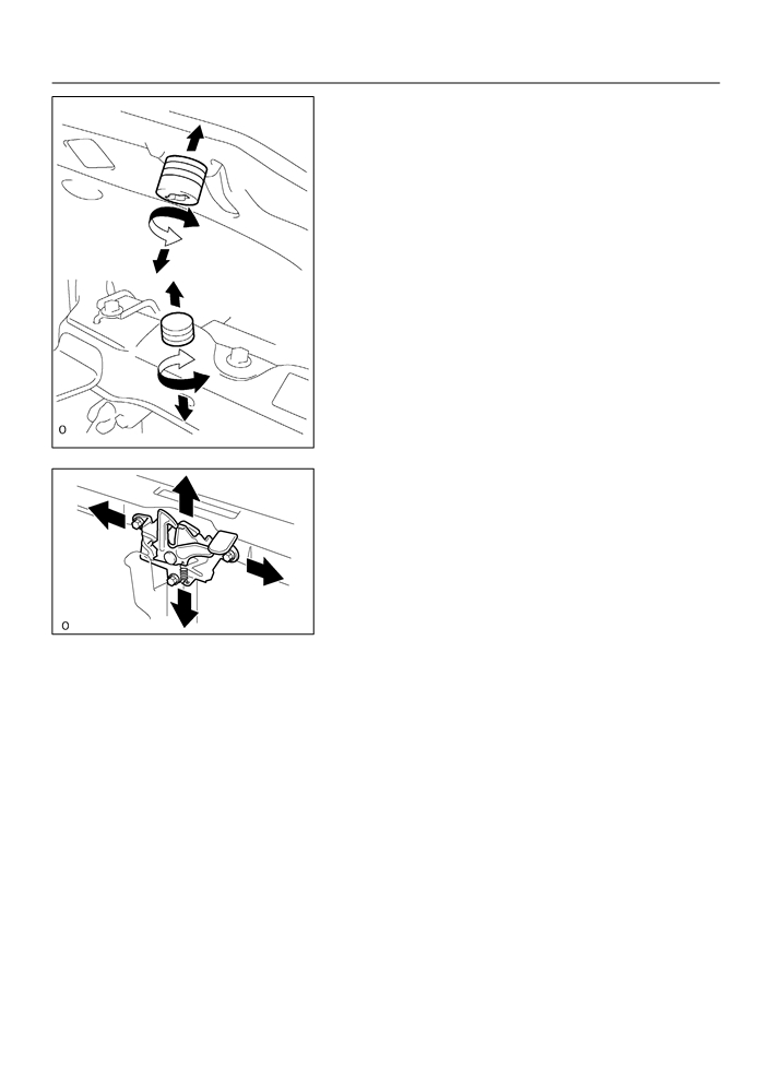
(b) Adjust the hood by turning the cushions.
B59029
(c)
Adjust the lock by loosening the 3 bolts.
Torque: 7.0 N·m (82 kgf·cm, 71 in.·lbf)
B50241

75-29
ENGINE HOOD/DOOR
- LUGGAGE DOOR HINGE TORSION BAR RH
LUGGAGE DOOR HINGE TORSION BAR RH
750DJ-02
REPLACEMENT
HINT:
F
Installation is in the reverse order of the removal. But the installation is indicated only when it has a
point.
F
In the LH side, work in the same procedure as in the RH side.
F
Since the removal of the torsion bar will cause no tension, operation of opening and closing the door
should be carried out holding the door by hand in order to prevent the door from closing without any
resistance.
F
RH side torsion bar is in the upper side and LH side torsion bar is in the lower side, thus the installation
should be done in the order of RH to LH, and the removal should be done in the order of LH to RH.
1.
REMOVE LUGGAGE DOOR HINGE TORSION BAR RH
(a) Remove the torsion bars from the center bracket.
(b) Install SST to the torsion bar on the hinge side.
SST
09804-24010
SST
B50229
(c)
Push down the SST, and pull the luggage compartment
door hinge from the torsion bar.
(d) Slowly lift the SST, and remove the torsion bar from the
torsion bar bracket with SST.
B50230
(e) Disconnect the torsion bar from the bracket.
(f)
Employ the same manner described above to the other
side.
B50231
2.
INSTALL LUGGAGE DOOR HINGE TORSION BAR RH
(a) When installing the torsion bar, be sure to install it to the clamp securely.

75-27
ENGINE HOOD/DOOR
- LUGGAGE COMPARTMENT DOOR
LUGGAGE COMPARTMENT DOOR
750DI-02
ADJUSTMENT
1.
INSPECT LUGGAGE COMPARTMENT DOOR PANEL SUB-ASSY
(a) Check that the clearance is within the standard value.
4.0
(0.157)
1.5
(0.059)
8.0
(0.315)
mm (in.)
B59012
2.
ADJUST LUGGAGE COMPARTMENT DOOR PANEL
SUB-ASSY
(a) For forward/rearward and right/left adjustments, loosen
the bolts.
Torque: 7.0 N·m (71 kgf·cm, 62 in.·lbf)
(b) For a vertical adjustment of the door front end, increase
or decrease the number of washers between the hinge
and door.
B50243
Torque: 7.0 N·m (71 kgf·cm, 62 in.·lbf)
(c)
Remove the spare wheel cover (See page 76-5).
(d) Remove the rear floor finish plate (See page 76-5).
(e) For forward/rearward and right/left adjustments, loosen
the bolts.
Torque: 5.5 N·m (56 kgf·cm, 49 in.·lbf)
(f)
Using a hammer and a brass bar, tap the striker to adjust
it.
B59013

75-28
ENGINE HOOD/DOOR
- LUGGAGE COMPARTMENT DOOR
(g) Perform the forward/rearward and right/left adjustments,
by loosening the bolts of the luggage compartment door.
Torque: 5.5 N·m (56 kgf·cm, 49 in.·lbf)
Luggage Compartment Door Lock Assy
B
8

75-18
ENGINE HOOD/DOOR
- REAR DOOR
750DH-02
ADJUSTMENT
HINT:
F
In the RH side, work in the same procedure as in the LH side.
F
Since the centering bolt is used as a door side hinge bolt,
the door hinge cannot be adjusted with it on. Substitute
the bolt with washer for the centering bolt.
Centering Bolt
Standard Bolt
N03433
1.
INSPECT REAR DOOR PANEL SUB-ASSY LH
(a) Check that the clearance is within the standard value.
G-G
G
129 (5.08)
42 (1.65)
F
F-F
A
B
G
C
F
D
A: 5.5 (0.217)
1.5
(0.059)
E
B: 5.6 (0.220)
1.5
(0.059)
C: 5.9 (0.232)
1.5
(0.059)
D: 6.0 (0.236)
1.5
(0.059)
E: 5.0 (0.197)
1.5
(0.059)
E
mm (in.)
E
B59011
2.
REMOVE FRONT DOOR SCUFF PLATE LH (See page 76-21)
3.
REMOVE REAR DOOR SCUFF PLATE LH (See page 76-21)
4.
REMOVE FRONT DOOR WEATHERSTRIP LH (See page 75-7)
5.
REMOVE REAR DOOR WEATHERSTRIP LH (See page 75-20)
6.
REMOVE CENTER PILLAR GARNISH LOWER LH (See page 76-21)