Toyota Corolla (2004+). Manual - part 93
14-110
ENGINE MECHANICAL
- CYLINDER HEAD GASKET
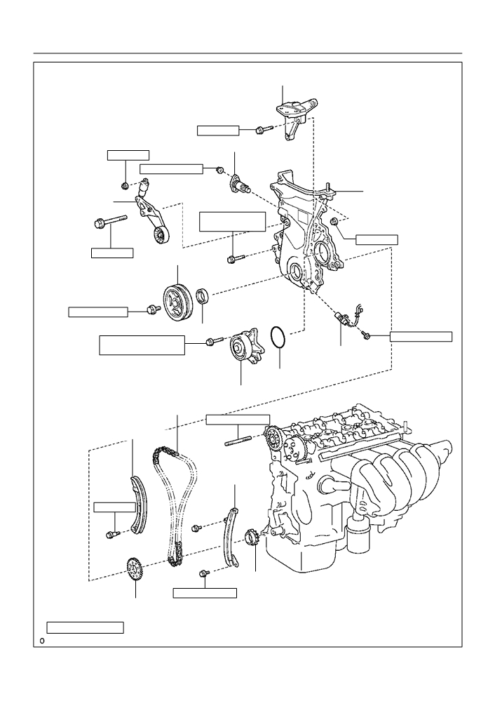
Transverse Engine
Engine Mounting Bracket
47 (479, 35)
Chain Tensioner Assy No. 1
29 (296, 21)
9.0 (92, 80 in. lbf)
Timing Chain or
V-ribbed Belt
Belt Cover Sub-assy
Tensioner Assy
13 (133, 10) (M6)
19 (194, 14) (M8)
13 (133, 10)
69 (704, 51)
Crankshaft Pulley
138 (1,047, 102)
_ Oil Seal
9.0 (92, 80 in. lbf)
9 (92, 80 in. lbf1) (L=20)
11 (112, 8) (L=35)
Crank Position Sensor
_ O-ring
Water Pump Assy
Chain Sub-assy
9.5 (97, 84 in. lbf)
Chain Tensioner Slipper
Chain Vibration
Damper No. 1
19 (194, 14)
Crankshaft timing Sprocket
9.0 (92, 80 in. lbf)
Crankshaft Position Sensor
Plate No. 1
N·m (kgf·cm, ft·lbf)
: Specified torque
_ Non-reusable part
A60628

14-111
ENGINE MECHANICAL
- CYLINDER HEAD GASKET
Camshaft Bearing Cap No. 1
13 (133, 10)
23 (235, 17)
Camshaft Bearing Cap No. 3
Camshaft No. 2
Camshaft
See page 14-112
1st 49 (500, 36)
2nd Turn 90 F
Plate Washer
Cylinder Head Sub-assy
_ O-ring
_ Gasket
Camshaft Timing Oil Control Valve Assy
9.0 (92, 80 in. lbf)
Intake Manifold
_ Cylinder Head Gasket
49 (500, 36)
Clamp Bracket
Manifold Stay
13 (133, 10)
30 (306, 22)
9.0 (92, 80 in. lbf)
Oil Level Gage
Sub-assy
Oil Level Gage Guide
_ O-ring
N·m (kgf·cm, ft·lbf)
: Specified torque
_ Non-reusable part
A64046

14-112
ENGINE MECHANICAL
- CYLINDER HEAD GASKET
140OL-01
REPLACEMENT
1.
WORK FOR PREVENTING GASOLINE FROM SPILLING OUT (See page 11-1)
2.
REMOVE ENGINE UNDER COVER RH
3.
DRAIN COOLANT (See page 16-7)
4.
REMOVE FRONT WHEEL RH
5.
REMOVE CYLINDER HEAD COVER NO.2
(a) Remove the 2 nuts, 2 clips and cylinder head cover.
A65077
6.
REMOVE AIR CLEANER HOSE NO.1
(a) Loosen the 2 air cleaner hose clamp bolts, and remove the air cleaner hose.
7.
SEPARATE ACCELERATOR CONTROL CABLE ASSY
(a) Loosen the nut, and remove the accelerator control cable from the accelerator control cable bracket.
8.
DISCONNECT WATER BY-PASS HOSE
(a) Disconnect the water by-pass hose from the throttle body.
9.
DISCONNECT WATER BY-PASS HOSE NO.2
(a) Disconnect the water by-pass hose from the throttle body.
10. REMOVE EFI FUEL PIPE CLAMP (See page 11-10)
11. DISCONNECT FUEL TUBE SUB-ASSY (See page 11-10)
SST
09268-21010
12. DISCONNECT UNION TO CONNECTOR TUBE HOSE
(a) Disconnect the union to connector tube hose from the hose to hose tube.
13. DISCONNECT RADIATOR HOSE INLET
(a) Disconnect radiator hose inlet from the cylinder head.
14. DISCONNECT HEATER INLET WATER HOSE
(a) Disconnect the heater inlet water hose from the cylinder head.
15. REMOVE FAN AND GENERATOR V BELT
(a) Turn the V-ribbed belt tensioner slowly clockwise and
loosen it. Then, remove the fan and generator V belt and
put back the V-ribbed belt tensioner little by little and fix
it quietly.
A60622
14-113
ENGINE MECHANICAL
- CYLINDER HEAD GASKET
16. SEPARATE VANE PUMP ASSY (See page 51-8)
NOTICE:
Do not disconnect the hose.
17. REMOVE GENERATOR ASSY (See page 19-16)
18. SEPARATE EXHAUST PIPE ASSY FRONT
(a) Remove the 2 bolts, 2 compression spring installing the front side of exhaust pipe.
(b) Remove the gasket.
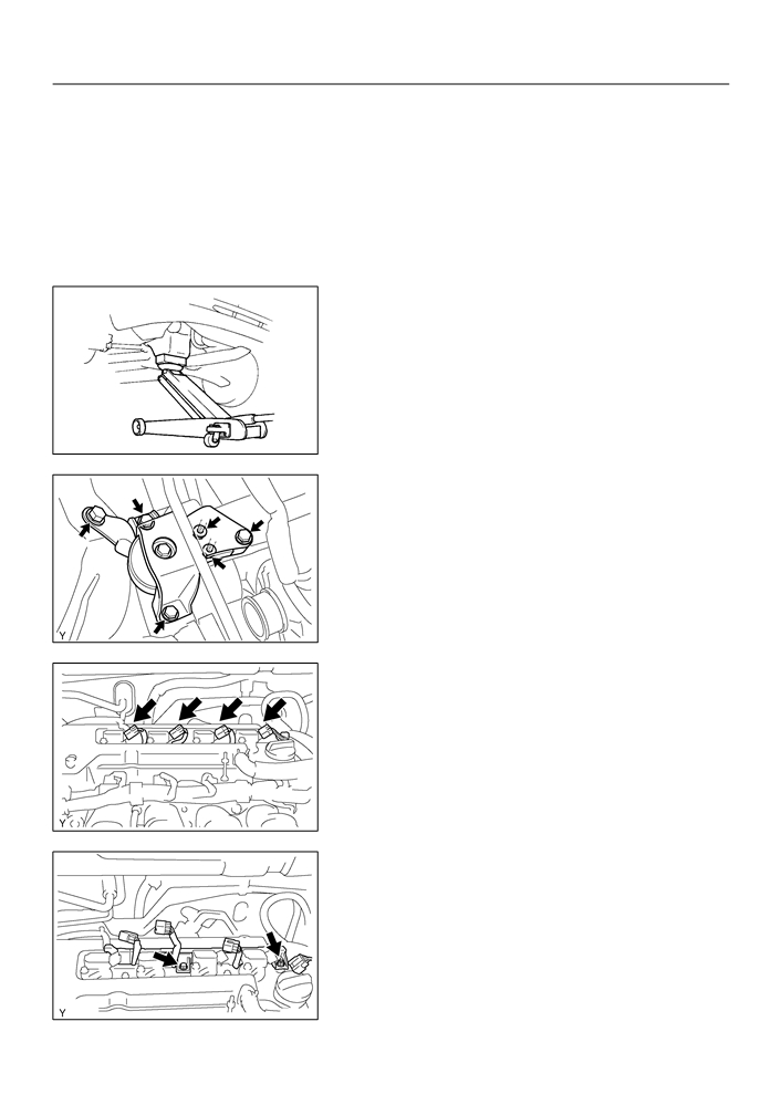
19. REMOVE ENGINE MOUNTING INSULATOR
SUB-ASSY RH
(a) Remove the PS oil pump reservoir and put it aside.
(b) Place a wooden block between the jack and engine, and
set the jack, then remove the 4 bolts, the 2 nuts and en-
gine mounting insulator RH.
A01045
A64005
20. DISCONNECT ENGINE WIRE
(a) Remove the 5 clamps from the 5 clamp brackets.
(b) Disconnect the 4 ignition coil connectors.
A64021
(c)
Remove the bolt and nut installing the engine wire.
A64022

14-114
ENGINE MECHANICAL
- CYLINDER HEAD GASKET
21. REMOVE IGNITION COIL ASSY
(a) Remove the 4 bolts and 4 ignition coils.
A64023
22. DISCONNECT VENTILATION HOSE
(a) Disconnect the ventilation hose from the cylinder head
cover.
A65078
23. DISCONNECT VENTILATION HOSE NO.2
(a) Disconnect the ventilation hose from the cylinder head
cover.
A64058
24. REMOVE CYLINDER HEAD COVER SUB-ASSY
(a) Remove the 9 bolts, 2 seal washers, 2 nuts, 3 clamp
brackets and cylinder head cover.
A64856
14-115
ENGINE MECHANICAL
- CYLINDER HEAD GASKET
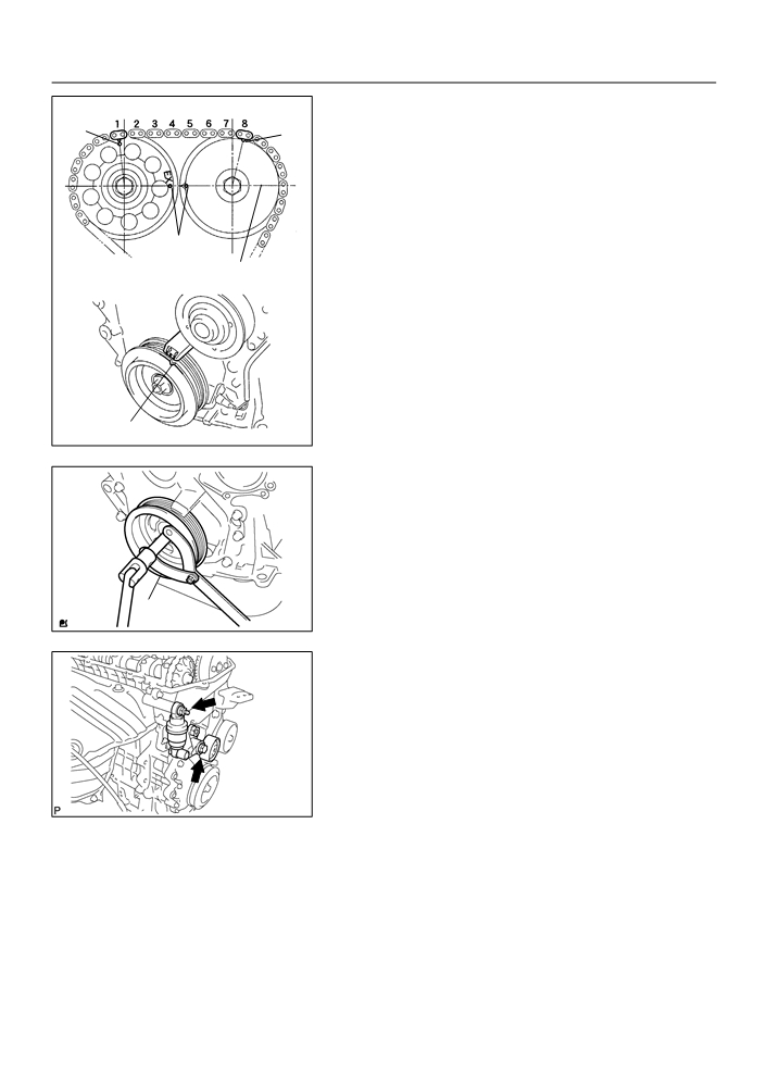
25. SET NO. 1 CYLINDER TO TDC/COMPRESSION
Mark
(a) Turn the crankshaft pulley, and align its groove with timing
Mark
mark ”0” of the timing chain cover.
(b) Check that the point marks of the camshaft timing sprock-
et and VVT timing sprocket are in straight line on the tim-
ing chain cover surface as shown in the illustration.
HINT:
If not, turn the crankshaft 1 revolution (360_) and align the
Mark
marks as above.
Timing Chain
Cover Surface
Groove
A62185
26. REMOVE CRANKSHAFT PULLEY
(a) Using SST, remove the pulley bolt.
SST
09960-10010 (09962-01000, 09963-01000)
(b) Remove the crankshaft pulley from the crankshaft.
SST
A62837
27. REMOVE V-RIBBED BELT TENSIONER ASSY
(a) Remove the bolt, nut and V-ribbed belt tensioner.
HINT:
Handle a jack up and down to remove the bolt.
A11858
28. REMOVE WATER PUMP ASSY (See page 16-8)
14-116
ENGINE MECHANICAL
- CYLINDER HEAD GASKET
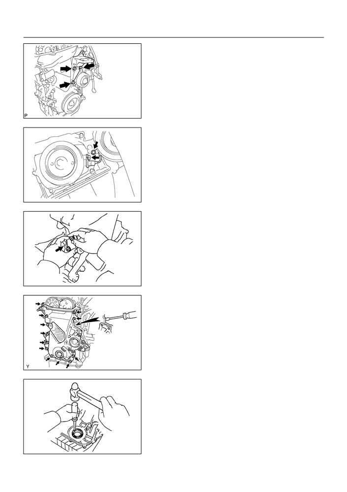
29. REMOVE TRANSVERSE ENGINE ENGINE
MOUNTING BRACKET
(a) Remove the 3 bolts and transverse engine engine mount-
ing bracket.
A12816
30. REMOVE CRANK POSITION SENSOR
(a) Remove the 2 bolts installing the crank position sensor.
B00086
31. REMOVE CHAIN TENSIONER ASSY NO.1
(a) Remove the 2 nuts and chain tensioner.
NOTICE:
Be sure not to revolve the crankshaft without the chain ten-
sioner.
Push
A62178
32. REMOVE TIMING CHAIN OR BELT COVER
SUB-ASSY
(a) Remove the 11 bolts and nuts.
(b) Using a torx wrench socket (E8), remove the stud bolt.
(c)
Remove the timing chain cover by prying the portions be-
tween the cylinder head and cylinder block with a screw-
driver.
NOTICE:
A10076
Be careful no tot damage the contact surfaces of the timing
chain cover, cylinder head and cylinder block.
33. REMOVE TIMING GEAR COVER OIL SEAL
(a) Using a screwdriver, remove the oil seal.
A30848

14-117
ENGINE MECHANICAL
- CYLINDER HEAD GASKET
34.
REMOVE CRANKSHAFT POSITION SENSOR PLATE NO.1
35.
REMOVE CHAIN TENSIONER SLIPPER
(a)
Remove the bolt and chain tensioner slipper.
36.
REMOVE CHAIN VIBRATION DAMPER NO.1
(a)
Remove the 2 bolt and chain vibration damper.
37. REMOVE CHAIN SUB-ASSY
(a) Remove the timing chain with the crankshaft timing gear
plying screwdrivers as shown in the illustration.
NOTICE:
F
Put shop rag to protect the engine.
F
In case of revolving the camshafts with the chain off
the sprockets, turn the crankshaft 1/4 revolution for
valves not to touch the pistons.
A30857
38. REMOVE INTAKE MANIFOLD
(a) Disconnect the 2 water hoses from the throttle body.
(b) Disconnect the 2 vacuum hoses from the intake man-
ihold.
(c)
Remove the 4 bolts, 2 nuts, 2 wire brackets, the intake
manihold and throttle body assembly.
(d) Remove the gasket from the intake manihold and throttle
body assembly.
A14660
39.
REMOVE OIL LEVEL GAGE SUB-ASSY
(a)
Remove the oil level gage from the oil level gage guide.
40. REMOVE OIL LEVEL GAGE GUIDE
(a) Remove the bolt and oil level gage guide.
A64026
41. SEPARATE WATER BY-PASS PIPE NO.1
(a) Remove the 2 bolts installing the water by-pass pipe.

14-118
ENGINE MECHANICAL
- CYLINDER HEAD GASKET
42. REMOVE CAMSHAFT
2
4
5
3
1
(a) Uniformly loosen and remove the 19 bearing cap bolts, in
several passes, in the sequence shown, and remove the
9 bearing caps, intake and exhaust camshafts.
A62814
43. REMOVE CAMSHAFT TIMING OIL CONTROL VALVE
ASSY
(a) Remove the bolt and camshaft timing oil control valve.
B06777
44. REMOVE MANIFOLD STAY
(a) Remove the 3 bolts and manifold stay.
A64030
45. REMOVE CYLINDER HEAD SUB-ASSY
3
7
9
6
2
(a) Using a 10 mm bi-hexagon wrench, uniformly loosen and
remove the 10 cylinder head bolts, in several passes, in
the sequence shown, and remove the 10 cylinder head
bolts and 10 plate washers.
(b) Remove the cylinder head.
1
5
10
8
4
A62816
46. REMOVE CYLINDER HEAD GASKET

14-119
ENGINE MECHANICAL
- CYLINDER HEAD GASKET
47. INSTALL CYLINDER HEAD GASKET
Lot No.
(a) Place a new cylinder head gasket on the cylinder block
surface with the Lot No. stamp upward.
NOTICE:
F
Pay attention to the installation direction.
F
Place the cylinder head quietly in order not to damage
the gasket with the bottom part of the head.
A62827
48. INSPECT CYLINDER HEAD SET BOLT
(a) Using a vernier calipers, measure the length of cylinder
Overall Length
head bolt from the seat to the end.
Standard length: 146.8 - 148.2 mm (5.780 - 5.835 in.)
Maximum length: 148.5 mm (5.846 in.)
If the length surpasses the maximum, replace the bolt.
A62820
49. INSTALL CYLINDER HEAD SUB-ASSY
8
4
2
5
9
HINT:
The cylinder head bolts are tightened in 2 progressive steps.
(a) Apply a light coat of engine oil on the threads and under
the heads of the cylinder head bolts.
(b) Using a 10 mm bi-hexagon wrench, install and uniformly
tighten the 10 cylinder head bolts and plate washers, in
several passes, in the sequence shown.
10
6
1
3
7
A62816
Torque: 49 N m (500 kgf cm, 36 ft lbf)
(c)
Make the front of the cylinder head bolt with paint.
Paint Mark
90_
(d) Retighten the cylinder head bolts 90_ in the numerical or-
der shown.
Front
(e) Check that the point marked bolts are moved at 90_
angle.
A62823
50. INSTALL MANIFOLD STAY
(a) Install the manifold stay with 3 bolts.
Torque: 49 N m (500 kgf cm, 36 ft lbf)
A64030

14-120
ENGINE MECHANICAL
- CYLINDER HEAD GASKET
51. INSTALL CAMSHAFT TIMING OIL CONTROL VALVE
ASSY
(a) Apply a light coat of engine oil on a new O-ring, and install
it to the camshaft timing oil control valve.
(b) Install the camshaft timing oil control valve with the bolt.
Torque: 9.0 N m (92 kgf cm, 80 in. lbf)
B06777
52. INSTALL CAMSHAFT
(a) Apply a light coat of engine oil on the camshaft journals.
(b) Place the 2 camshafts on the cylinder head with the No.
1 cam lobes facing as shown the illustration.
A62150
(c)
Examine the front marks and numbers and tighten the
6
2
4
8
bolts in the order shown in the illustration.
Torque:
11
Bearing cap No. 1 23 N m (235 kgf cm, 17 ft lbf)
10
Bearing cap No. 3 13 N m (133 kgf cm, 10 ft lbf)
9
5
1
3
7
A62825
53. INSTALL WATER BY-PASS PIPE NO.1
(a) Install the water by-pass pipe with the 2 bolts.
Torque: 9.0 N m (92 kgf cm, 80 in. lbf)
54. INSTALL OIL LEVEL GAGE GUIDE
(a) Apply a light coat of engine oil on a new O-ring, and install
it to the oil level gage guide.
(b) Install the oil level gage guide with the bolt.
Torque: 13 N m (133 kgf cm, 10 ft lbf)
A64026

14-121
ENGINE MECHANICAL
- CYLINDER HEAD GASKET
55. INSTALL INTAKE MANIFOLD
(a) Install a new gasket to the intake manifold.
(b) Install the intake manifold and throttle body assembly with
the 2 brackets, 4 bolts and 2 nuts. Uniformly tighten the
bolts and nuts in several passes.
Torque: 30 N m (306 kgf cm, 22 ft lbf)
(c)
Connect the 2 vacuum hoses to the intake manifold.
(d) Connect the 2 water hoses to the throttle body.
A14660
56. INSTALL CHAIN SUB-ASSY
(a) Set No. 1 cylinder to TDC/compression.
(1)
Turn the hexagonal wrench head portion of the
camshafts, and align the point marks of the cam-
shaft timing sprockets.
A10079
(2)
Using a crankshaft pulley bolt, turn the crankshaft
Upward
Set Key
and set the set key on the crankshaft upward.
A62170
(b) Install the timing chain on the crankshaft timing sprocket
Yellow
with the yellow color link aligned with the timing mark on
Color Line
the crankshaft timing sprocket.
HINT:
Three yellow color links are on the chain.
Timing Mark
A62171
(c)
Using SST, install the crankshaft timing sprocket.
SST
09223-22010
SST
A62172

14-122
ENGINE MECHANICAL
- CYLINDER HEAD GASKET
Yellow Color Mark
(d) Install the timing chain on the camshaft timing sprockets
with the yellow color links aligned with the timing marks on
the camshaft timing sprockets.
Timing Mark
A62173
57. INSTALL CHAIN VIBRATION DAMPER NO.1
(a) Install the chain vibration damper with the 2 bolts.
Torque: 9.0 N m (92 kgf cm, 80 in. lbf)
58. INSTALL CHAIN TENSIONER SLIPPER
(a) Install the chain tensioner slipper with the bolt.
Torque: 19 N m (194 kgf cm, 14 ft lbf)
59. INSTALL CRANKSHAFT POSITION SENSOR PLATE
NO.1
(a) Install the plate with the ”F” mark facing forward.
A30867
60. INSTALL TIMING GEAR COVER OIL SEAL
(a) Apply MP grease to a new oil seal lip.
SST
(b) Using SST, tap in the oil seal until its surface is flush with
the timing chain cover edge.
SST
09223-22010
NOTICE:
Keep the lip off foreign materials.
A62174
14-123
ENGINE MECHANICAL
- CYLINDER HEAD GASKET
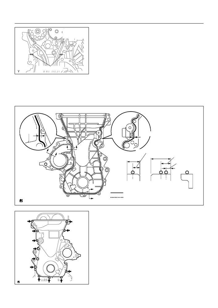
61. INSTALL TIMING CHAIN OR BELT COVER SUB-ASSY
Seal Width
(a) Remove any old packing material from the contact sur-
4 - 5 mm
face.
(b) Apply seal packing in the shape of bead (Diameter 3.5
mm - 4.5 mm (0.1379 - 0.177 in.)) consequently as
shown in the illustration.
Seal packing:
Water pump part part No. 08826-00100 or equivalent
Seal Packing
A62175
Other part part No. 08826-00080 or equivalent.
NOTICE:
F
Remove any oil from the contact surface.
F
Install the oil pan within 3 minutes after applying seal
packing.
F
Do not put into engine oil within 2 hours after instal-
ling.
Timing Chain Cover side:
3 (0.118)
3 (0.118)
B
B
4.5
(0.177)
A
12 (0.472)
6 (0.236)
A
7 (0.276)
3 (0.118)
Width 4 (0.157)
A - A
B - B
C
08826-00100 or equivalent
C - C
08826-00080 or equivalent
(mm (in.))
C
A65676
(c)
Install the timing chain cover with the 11 bolts and nut.
Torque:
A
A
A 13 Nm (133 kgf cm, 10 ft lbf)
B 19 Nm (194 kgf cm, 14 ft lbf)
A
A
(d) Using a torx wrench socket (E8), install the stud bolt.
Torque: 9.5 N m (97 kgf cm, 84 in. lbf)
A
B
B
B
A
A
A
A
A65677

14-124
ENGINE MECHANICAL
- CYLINDER HEAD GASKET
62. INSTALL CHAIN TENSIONER ASSY NO.1
(a) Check the O-ring is clean, and set the hook as shown in
Raise
the illustration.
Push
Hook
Pin
A62177
(b) Apply engine oil to the chain tensioner and install it withe
2 nuts.
Torque: 9.0 N m (92 kgf cm, 80 in. lbf)
NOTICE:
When installing the tensioner, set the hook again if the
Push
hook release the plunger.
A62178
63. INSTALL CRANK POSITION SENSOR
(a) Install the crank position sensor with the 2 bolts.
Torque: 9.0 N m (92 kgf cm, 80 in. lbf)
B00086
64. INSTALL TRANSVERSE ENGINE ENGINE MOUNTING
BRACKET
(a) Install the transverse engine engine mounting bracket
with the 3 bolts.
Torque: 47 N m (479 kgf cm, 35 ft lbf)
A12816
65. INSTALL WATER PUMP ASSY (See page 16-8)