Toyota Corolla (2004+). Manual - part 94
14-125
ENGINE MECHANICAL
- CYLINDER HEAD GASKET
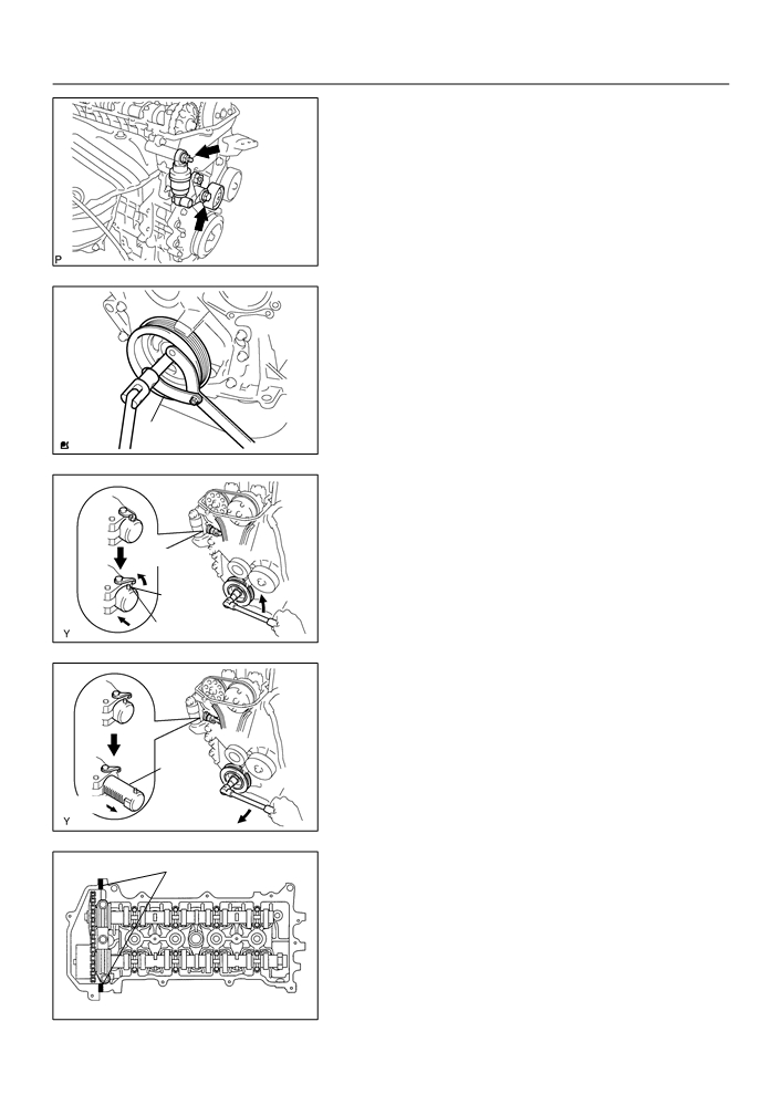
66. INSTALL V-RIBBED BELT TENSIONER ASSY
(a) Install the V-ribbed belt tensioner with the nut and bolt.
Torque:
Nut 29 N m (296 kgf cm, 21 ft lbf)
Bolt 69 N m (704 kgf cm, 51 ft lbf)
A11858
67. INSTALL CRANKSHAFT PULLEY
(a) Align the pulley set key with the key groove of the pulley,
and slide on the pulley.
(b) Using SST, install the crankshaft pulley bolt.
SST
09960-10010 (09962-01000, 09963-01000)
Torque: 138 N m (1,407 kgf cm, 102 ft lbf)
SST
A62837
(c)
Turn the crankshaft counter clockwise, and disconnect
the plunger knock pin form the hook.
Disconnect
Hook
Pin
Turn
A62180
(d) Turn the crankshaft clockwise, and check that the slipper
is pushed by the plunger.
HINT:
If the plunger does not spring out, press the slipper into the
chain tensioner with a screwdriver so that the hook is released
from the knock pin and the plunger springs out.
Plunger
Push
Turn
A62181
68. INSTALL CYLINDER HEAD COVER SUB-ASSY
Seal Packing
(a) Remove any old pacing (FIPG) material.
(b) Apply seal packing to 2 locations as shown in the illustra-
tion.
Seal packing: Part No. 08826-00080 or equivalent
NOTICE:
F
Remove any oil from the contact surface.
F
Install the cylinder head cover within 3 minutes after
A62182
applying seal packing.
F
Do not put into engine oil 2 hours after installing.

14-126
ENGINE MECHANICAL
- CYLINDER HEAD GASKET
(c)
Install the cylinder head cover and 3 cable brackets with
A
A
A
the 9 bolts, 2 seal washers and 2 nuts. Uniformly tighten
the bolts and nuts, in the several passes.
A
Torque:
B
B
A 11 Nm (112 kgf cm, 8 ft lbf)
B 9.0 Nm (92 kgf cm, 80 in. lbf)
A
A
A
A
A
A65687
69. INSTALL IGNITION COIL ASSY
(a) Install the 4 ignition coils with the 4 bolts.
Torque: 9.0 N m (92 kgf cm, 80 in. lbf)
A64023
70. INSTALL ENGINE WIRE
(a) Install the engine wire with the bolt and nut.
Torque: 9.0 N m (92 kgf cm, 80 in. lbf)
A64022
71. INSTALL ENGINE MOUNTING INSULATOR
SUB-ASSY RH
(a) Install the engine mounting insulator with the 4 bolts and
2 nuts.
Torque: 52 N m (530 kgf cm, 38 ft lbf)
A64005

14-127
ENGINE MECHANICAL
- CYLINDER HEAD GASKET
72. INSTALL EXHAUST PIPE ASSY FRONT (See page 15-2)
73. INSTALL VANE PUMP ASSY (See page 51-8)
74. INSTALL GENERATOR ASSY (See page 19-16)
75. INSTALL CYLINDER HEAD COVER NO.2
(a) Install the cylinder head cover with the 2 nuts and 2 clips.
Torque: 7.0 N m (71 kgf cm, 62 in. lbf)
A65077
76. INSTALL FRONT WHEEL RH
Torque: 103 N m (1,050 kgf cm, 76 ft lbf)
77. ADD COOLANT (See page 16-7)
78. INSPECT COMPRESSION (See page 14-1)
SST
09992-00500
79. INSPECT CO/HC (See page 14-1)
80. INSPECT IGNITION TIMING (See page 14-1)
SST
09843-18040
81. CHECK ENGINE COOLANT LEAK (See page 16-7)
82. CHECK ENGINE OIL LEAK

14-133
ENGINE MECHANICAL
- CYLINDER HEAD ASSY
CYLINDER HEAD ASSY
140Q6-02
COMPONENTS
Valve Lifter
Valve Spring Retainer Lock
Valve Spring Retainer
Inner Compression Spring
F Valve Stem Oil O Seal or Ring
F Exhaust Valve Guide Bush
Valve Spring Seat
F Intake Valve Guide Bush
W/ Head Taper Screw Plug No. 2
44 (449, 33)
5.0 (51, 44 in. lbf)
F Gasket
F Ring Pin
F Union
9.5 (97, 84 in. lbf)
F Union
9.5 (97, 84 in. lbf)
F Union
5.0 (51, 44 in. lbf)
Cylinder Head Sub-assy
9.5 (97, 84 in. lbf)
Intake Valve
Exhaust Valve
N·m (kgf·cm, ft·lbf)
: Specified torque
F Non-reusable part
A62766

14-134
ENGINE MECHANICAL
- CYLINDER HEAD ASSY
140Q7-04
OVERHAUL
1.
REMOVE W/HEAD TAPER SCREW PLUG NO.2
(a) Using a socket hexagon wench 10, remove the taper
screw plug and gasket.
A62890
2.
REMOVE VALVE LIFTER
(a) Remove the valve lifters from the cylinder head.
A62891
3.
REMOVE VALVE
SST
(a) Place the cylinder head on wooden blocks.
(b) Using SST, compress the inner compression spring and
Wooden
remove the 2 valve spring retainer locks.
Block
SST
09202-70020 (09202-00010, 09202-01010,
09202-01020)
(c)
Remove the valve spring retainers, inner compression
springs and valves from the cylinder head.
A65688
4.
VALVE STEM OIL O SEAL OR RING
(a) Using a needle-nose pliers, remove the valve stem oil
seals.
A62893

14-135
ENGINE MECHANICAL
- CYLINDER HEAD ASSY
5.
REMOVE VALVE SPRING SEAT
(a) Using a compressed air and a magnetic finger, remove
the valve spring seats.
A62894
6.
REMOVE STUD BOLT
(a) Using torx socket wrench E5 and E7, remove the 11 stud bolts.
Upper side:
Front side:
Exhaust side:
Intake side:
A65689
7.
INSPECT CYLINDER HEAD FOR FLATNESS
(a) Using a precision straight edge and a feeler gauge, mea-
sure the surface contacting the cylinder block and the
manifolds for warpage.
Maximum warpage:
Cylinder block side 0.05 mm (0.0020 in.)
Intake manifold side 0.10 mm (0.0039 in.)
Cylinder block side:
Exhaust manifold side 0.10 mm (0.0039 in.)
If the warpage is greater than maximum, replace the cylinder
head.
Intake manifold side:
Exhaust manifold side:
A65690

14-136
ENGINE MECHANICAL
- CYLINDER HEAD ASSY
8.
INSPECT CYLINDER HEAD FOR CRACKS
(a) Using a dye penetrate, check the combustion chamber,
intake ports, exhaust ports and cylinder block surface for
cracks.
A62897
9.
INSPECT VALVE SEATS
(a) Apply a light coat of prussian blue (or white lead) to the
valve face.
(b) Lightly press the valve against the seat.
NOTICE:
Width
Do not rotate valve.
(c)
Check the valve face and seat according to the following
procedure.
A62786
(1)
If blue appears 360_ around the face, the valve is
concentric. If not, replace the valve.
(2)
If blue appears 360_ around the valve seat, the
guide and face are concentric. If not, resurface the
seat.
(3)
Check that the seat contact is in the middle of the
valve face with the width between 1.0 - 1.4 mm
(0.039 - 0.055 in.).
10. REPAIR VALVE SEATS
NOTICE:
45_
Take off a cutter gradually to make smooth valve seats.
(a) If the seating is too high on the valve face, use 30_ and
30_
45_ cutters to correct the seat.
1.0 - 1.4 mm
(0.039 - 0.055 in.)
A62787

14-137
ENGINE MECHANICAL
- CYLINDER HEAD ASSY
(b) Intake:
Intake:
(1)
If the seating is too low on the valve face, use 60_
60_
and 45_ cutters to correct the seat.
(c)
Exhaust:
45_
(1)
If the seating is too low on the valve face, use 75_
and 45_ cutters to correct the seat.
(d) Hand-lap the valve and valve seat with an abrasive com-
pound.
1.0 - 1.4 mm
(e) Check the valve seating position.
(0.039 - 0.055 in.)
Exhaust:
75_
45_
1.0 - 1.4 mm
(0.039 - 0.055 in.)
A65691
11. INSPECT CAMSHAFT THRUST CLEARANCE
(a) Install the 2 camshafts.
(b) Using a dial indicator, measure the thrust clearance while
moving the camshaft back and forth.
Standard thrust clearance:
0.040 - 0.095 mm (0.0016 - 0.0037 in.)
Maximum thrust clearance: 0.110 mm (0.0043 in.)
If the thrust clearance is greater than maximum, replace the cyl-
A62900
inder head. If damages are found on the camshaft thrust sur-
faces, the camshaft also has to be replaced.
12. INSPECT CAMSHAFT OIL CLEARANCE
Plastigage
(a) Clean the bearing caps and camshaft journals.
(b) Place the camshafts on the cylinder head.
(c)
Lay a strip of plastigage across each of the camshaft jour-
nal.
(d) Install the bearing caps. (See page 14-45)
NOTICE:
Do not turn the camshaft.
A65692
(e) Remove the bearing caps. (See page 14-45)
(f)
Measure the plastigage at its widest point.
Standard oil clearance:
0.035 - 0.072 mm (0.0014 - 0.0028 in.)
Maximum oil clearance: 0.10 mm (0.0039 in.)
NOTICE:
Completely remove the plastigage after the measuring.
If the oil clearance is greater than maximum, replace the cylin-
der head.
A62902

14-138
ENGINE MECHANICAL
- CYLINDER HEAD ASSY
13. INSPECT VALVE LIFTER
(a) Using a micrometer, measure the valve lifter diameter.
Lifter diameter:
30.966 - 30.976 mm (1.2191 - 1.2195 in.)
P16860
14. INSPECT VALVE LIFTER OIL CLEARANCE
(a) Using a caliper gauge, measure the valve lifter bore diam-
eter of the cylinder head.
Lifter bore diameter:
31.000 - 31.025 mm (1.2205 - 1.2215 in.)
(b) Subtract the valve lifter diameter measurement from the
valve lifter bore diameter measurement.
Standard oil clearance:
A62903
0.024 - 0.059 mm (0.0009 - 0.0023 in.)
Maximum oil clearance: 0.079 mm (0.0031 in.)
If the oil clearance is greater than maximum, replace the valve
lifter.
If necessary, replace the cylinder head.
15. INSPECT INNER COMPRESSION SPRING
(a) Using a vernier caliper, measure the free length of the in-
ner compression spring.
Free length: 43.40 mm (1.7087 in.)
EM0801
(b) Using a steel square, measure the deviation of the inner
Deviation
compression spring.
Maximum deviation: 1.6 mm (0.063 in.)
Maximum angle (reference): 2
_
If the deviation is greater than maximum, replace the inner com-
pression spring.
A62784

14-139
ENGINE MECHANICAL
- CYLINDER HEAD ASSY
(c)
Using a spring tester, measure the tension of the inner
compression spring at the specified installed length.
Installed tension:
158.6 - 175.4 N (16.2 - 17.9 kgf, 35.7 - 39.5 lbf)
at 33.6 mm (1.323 in.)
Maximum working tension:
335.3 - 370.7 N (34.2 - 37.8 kgf, 75.4 - 83.3 lbf)
at 24.1 mm (0.949 in.)
EM0281
If the installed tension is not as specified, replace the inner com-
pression spring.
16. INSPECT VALVE
(a) Using a vernier calipers, check the valve overall length.
Standard overall length:
Intake 88.65 mm (3.4902 in.)
Overall
Exhaust 88.69 mm (3.4917 in.)
length
Minimum overall length:
Intake 88.35 mm (3.4784 in.)
Exhaust 88.39 mm (3.4799 in.)
EM2534
If the overall length is less than minimum, replace the valve.
(b) Using a micrometer, measure the diameter of the valve
stem.
Valve stem diameter:
Intake 5.470 - 5.485 mm (0.2154 - 0.2159 in.)
Exhaust 5.465 - 5.480 mm (0.2152 - 0.2158 in.)
A62783
(c)
Using a vernier calipers, check the valve head margin
thickness.
Standard margin thickness: 1.0 mm (0.039 in.)
Minimum margin thickness: 0.7 mm (0.028 in.)
If the overall length is less than minimum, replace the valve.
Margin
Thickness
A62785
17. INSPECT VALVE GUIDE BUSHING OIL CLEARANCE
(a) Using a caliper gauge, measure the inside diameter of the
valve guide bush.
Busing inside diameter:
5.510 - 5.530 mm (0.2169 - 0.2177 in.)
A62905

14-140
ENGINE MECHANICAL
- CYLINDER HEAD ASSY
(b) Subtract the valve stem diameter measurement from the
guide bushing inside diameter measurement.
Standard oil clearance:
Intake 0.025 - 0.060 mm (0.0010 - 0.0024 in.)
Exhaust 0.030 - 0.065 mm (0.0012 - 0.0026 in.)
Maximum oil clearance:
Intake 0.08 mm (0.0032 in.)
Exhaust 0.10 mm (0.0039 in.)
If the oil clearance is greater than maximum, replace the valve
and valve guide bushing.
18. REPLACE VALVE GUIDE BUSHING
(a) Heat the cylinder head to 80 - 100_C (176 - 212_F).
A62906
(b) Place the cylinder head on the wooden blocks.
SST
(c)
Using SST, tap out the valve guide bushing.
SST
09201-10000, 09201-01055, 09950-70010
(09951-07100)
Wooden
A65693
Block
(d) Using a caliper gauge, measure the bushing bore diame-
ter of the cylinder head.
Diameter: 10.285 - 10.306 mm (0.4049 - 0.4058 in.)
If the bushing bore diameter of the cylinder head is greater than
10.306 mm (0.4058 in.), machine the bushing bore to the di-
mension of 10.335 - 10.356 mm (0.4069 - 0.4077 in.) to install
a over size valve guide bushing.
HINT:
A62908
Valve guide bushing size
Bushing bore diameter mm (in.)
STD
10.285 - 10.306 (0.4049 - 0.4058)
O/S 0.05
10.335 - 10.356 (0.4069 - 0.4077)

14-141
ENGINE MECHANICAL
- CYLINDER HEAD ASSY
(e) Heat the cylinder head to 80 - 100_C (176 - 212_F).
A62906
(f)
Place the cylinder head on wooden blocks.
SST
(g) Using SST, tap in a new valve guide bushing to the speci-
fied protrusion height.
SST
09201-10000, 09201-01055, 09950-70010
(09951-07100)
Protrusion height: 8.7 - 9.1 mm (0.343 - 0.358 in.)
Wooden
A65694
Block
(h) Using a sharp 5.5 mm reamer, ream the valve guide bush-
ing to obtain the standard specified clearance.
Standard oil clearance:
Intake 0.025 - 0.060 mm (0.0010 - 0.0024 in.)
Exhaust 0.030 - 0.065 mm (0.0012 - 0.0026 in.)
A65582
19. INSTALL STRAIGHT PIN
(a) Using a plastic hammer, install the new 2 straight pins.
Standard protrusion: 5 mm (0.197 in.)
6
5 (0.197)
14
(mm (in.))
A65695

14-142
ENGINE MECHANICAL
- CYLINDER HEAD ASSY
20. INSTALL UNION
14 (0.551)
(a) Mark the standard position away from the edge, onto the
water hose union as shown in the illustration.
23.2
(0.913)
A
9 (0.354)
B
(mm (in.))
C
A62791
(b) Apply adhesive to the water hose union hole of the cylin-
Adhesive
der head.
Adhesive:
Part No. 08833-00070, THREE BOND 1324 or equiva-
lent.
A62792
(c)
Using a press, press in a new water hose union until the
standard marks come to the level of the cylinder head sur-
B
face.
Standard protrusion:
A
A 29 mm (1.142 in.)
B 66.5 mm (2.618 in.)
C
C 24 mm (0.945 in.)
NOTICE:
A62793
F
Install the water hose union within 3 minutes after ap-
plying adhesive.
F
Do not put into coolant within an hour after installing.

14-143
ENGINE MECHANICAL
- CYLINDER HEAD ASSY
21. INSTALL STUD BOLT
(a) Using torx socket wrench E5 and E7, install the 11 stud bolts,
Torque:
Stud bolt A, D and E 9.5 N m (97 kgf cm, 84 in. lbf)
Stud bolt B and C 5.0 N m (51 kgf cm, 44 in. lbf)
Upper side:
Front side:
B
A
C
Exhaust side:
Intake side:
20
D
E
93.5
30
24
15
18
53.5
49.5
38.5
40.5
16
16
13
9
12
A
B
C
D
E
(mm)
A65696
22. INSTALL VALVE SPRING SEAT
(a) Install the valve spring seats to the cylinder head.
A65581

14-144
ENGINE MECHANICAL
- CYLINDER HEAD ASSY
23. INSTALL VALVE STEM OIL O SEAL OR RING
(a) Apply a light coat of engine oil to a new valve stem oil
SST
seals.
NOTICE:
Be very careful to assemble the oil seal for intake and ex-
haust. Assembling the wrong one may cause a failure.
HINT:
The intake valve stem oil seal is gray and exhaust valve stem
oil seal is black.
(b) Using SST, push in the valve stem oil seals.
Gray Surface
Black Surface
SST
09201-41020
Intake:
Exhaust:
A65697
24. INSTALL VALVE
SST
(a) Place the cylinder head on wooden blocks.
(b) Install the valves, inner compression springs and valve
Wooden
spring retainers to the cylinder head.
Block
(c)
Using SST, compress the inner compression spring, and
place the 2 valve spring retainer locks around the valve
stem.
SST
09202-70020 (09202-00010, 09202-01010,
A65688
09202-01020)
(d) Using a pin punch 5, lightly tap the valve stem tip to en-
Pin Punch 5
sure a proper fit.
NOTICE:
Be careful not to damage the valve stem tip.
A65698
25. INSTALL VALVE LIFTER
(a) Apply a light coat of engine oil to the valve lifters.
(b) Install the valve lifters to the cylinder head.
A62891