Toyota Corolla (2004+). Manual - part 91

14-89
ENGINE MECHANICAL
- CHAIN SUB-ASSY
(c)
Install the timing chain cover with the 11 bolts and nut.
Torque:
A
A
A:
13 N m (133 kgf cm, 10 ft lbf)
B:
19 N m (194 kgf cm, 14 ft lbf)
A
A
(d) Using a torx wrench socket (E8), install the stud bolt.
Torque: 9.5 N m (97 kgf cm, 84 in. lbf)
A
B
B
B
A
A
A
A
A65677
31. INSTALL CHAIN TENSIONER ASSY NO.1
(a) Check the O-ring is clean, and set the hook as shown in
Raise
the illustration.
Push
Hook
Pin
A62177
(b) Apply engine oil to the chain tensioner and install it withe
2 nuts.
Torque: 9.0 N m (92 kgf cm, 80 in. lbf)
NOTICE:
When installing the tensioner, set the hook again if the
Push
hook release the plunger.
A62178
32. INSTALL CRANK POSITION SENSOR
(a) Install the crank position sensor with the 2 bolts.
Torque: 9.0 N m (92 kgf cm, 80 in. lbf)
B00086

14-90
ENGINE MECHANICAL
- CHAIN SUB-ASSY
33. INSTALL TRANSVERSE ENGINE ENGINE MOUNTING
BRACKET
(a) Install the transverse engine engine mounting bracket
with the 3 bolts.
Torque: 47 N m (479 kgf cm, 35 ft lbf)
A12816
34. INSTALL WATER PUMP ASSY (See page 16-8)
35. INSTALL V-RIBBED BELT TENSIONER ASSY
(a) Install the V-ribbed belt tensioner with the nut and bolt.
Torque:
Nut 29 N m (296 kgf cm, 21 ft lbf)
Bolt 69 N m (704 kgf cm, 51 ft lbf)
A11858
36. INSTALL CRANKSHAFT PULLEY
(a) Align the pulley set key with the key groove of the pulley,
and slide on the pulley.
(b) Using SST, install the crankshaft pulley bolt.
SST
09960-10010 (09962-01000, 09963-01000)
Torque: 138 N m (1,407 kgf cm, 102 ft lbf)
SST
A62837
(c)
Turn the crankshaft counter clockwise, and disconnect
the plunger knock pin form the hook.
Disconnect
Hook
Pin
Turn
A62180

14-91
ENGINE MECHANICAL
- CHAIN SUB-ASSY
(d) Turn the crankshaft clockwise, and check that the slipper
is pushed by the plunger.
HINT:
If the plunger does not spring out, press the slipper into the
chain tensioner with a screwdriver so that the hook is released
from the knock pin and the plunger springs out.
Plunger
Push
Turn
A62181
37. INSTALL CYLINDER HEAD COVER SUB-ASSY
Seal Packing
(a) Remove any old pacing (FIPG) material.
(b) Apply seal packing to 2 locations as shown in the illustra-
tion.
Seal packing: Part No. 08826-00080 or equivalent
NOTICE:
F
Remove any oil from the contact surface.
F
Install the cylinder head cover within 3 minutes after
A62182
applying seal packing.
F
Do not put into engine oil 2 hours after installing.
(c)
Install the cylinder head cover and 3 cable brackets with
A
A
A
the 9 bolts, 2 seal washers and 2 nuts. Uniformly tighten
the bolts and nuts, in the several passes.
A
Torque:
B
B
A 11 Nm (112 kgf cm, 8 ft lbf)
B 9.0 Nm (92 kgf cm, 80 in. lbf)
A
A
A
A
A
A65687
38. INSTALL IGNITION COIL ASSY
(a) Install the 4 ignition coils with the 4 bolts.
Torque: 9.0 N m (92 kgf cm, 80 in. lbf)
A64023

14-92
ENGINE MECHANICAL
- CHAIN SUB-ASSY
39. INSTALL ENGINE WIRE
(a) Install the engine wire with the bolt and nut.
Torque: 9.0 N m (92 kgf cm, 80 in. lbf)
A64022
40. INSTALL ENGINE MOUNTING INSULATOR
SUB-ASSY RH
(a) Install the engine mounting insulator with the 4 bolts and
2 nuts.
Torque: 52 N m (530 kgf cm, 38 ft lbf)
A64005
41. INSTALL GENERATOR ASSY (See page 51-8)
42. INSTALL VANE PUMP ASSY (See page 51-8)
43. INSTALL CYLINDER HEAD COVER NO.2
(a) Install the cylinder head cover with the 2 nuts and 2 clips.
Torque: 7.0 N m (71 kgf cm, 62 in. lbf)
A65077
44. INSTALL FRONT WHEEL RH
Torque: 103 N m (1,050 kgf cm, 76 ft lbf)
45. ADD COOLANT (See page 16-7)
46. CHECK ENGINE COOLANT LEAK (See page 16-7)
47. CHECK ENGINE OIL LEAK
14-146
ENGINE MECHANICAL
- CYLINDER BLOCK ASSY (April, 2003)
CYLINDER BLOCK ASSY (April, 2003)
140Q8-05
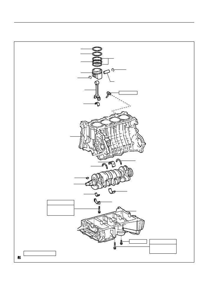
COMPONENTS
Compression Ring No. 1
Compression Ring No. 2
Oil Ring (Side Rail)
Oil Ring (Expander)
_ Snap Ring
Piston
_ Snap Ring
Piston Pin
Connecting Rod
25 (255, 18)
Cylinder Block Water Drain Cock Sub-assy
Connecting Rod Bearing
Cylinder Block Sub-assy
Crankshaft
Crankshaft Bearing
Thrust Washer Upper
Crankshaft Thrust Washer Upper
Key
Crankshaft
Crankshaft Bearing
Connecting Rod Bearing
See page 14-147
Connecting Rod Bearing Cap
1st 20 (204, 15)
Crankshaft Bearing Cap Sub-assy
2nd Turn 90 F
19 (194, 14)
See page 14-147
1st 44 (449, 33)
2nd Turn 90 F
N·m (kgf·cm, ft·lbf)
: Specified torque
_ Non-reusable part
A84914
14-147
ENGINE MECHANICAL
- CYLINDER BLOCK ASSY (April, 2003)
140Q9-05
OVERHAUL
1.
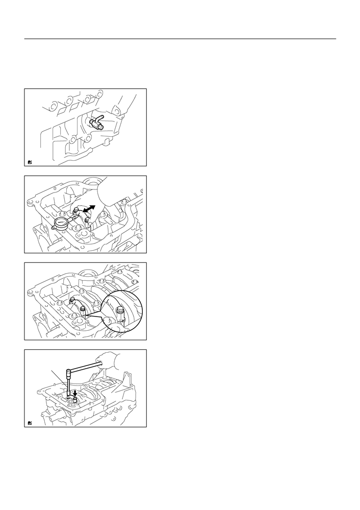
REMOVE CYLINDER BLOCK WATER DRAIN COCK
SUB-ASSY
(a) Remove the cylinder block water drain cock from the cyl-
inder block.
A64807
2.
INSPECT CONNECTING ROD THRUST CLEARANCE
(a) Using a dial indicator, measure the thrust clearance while
moving the connecting rod back and forth.
Standard thrust clearance:
0.160 to 0.342 mm (0.0063 to 0.0135 in.)
Maximum thrust clearance:
0.342 mm (0.0135 in.)
F
If the thrust clearance is greater than maximum, re-
A01155
place the connecting rod.
F
If necessary, replace the crankshaft.
3.
INSPECT CONNECTING ROD OIL CLEARANCE
NOTICE:
Do not turn the crankshaft.
(a) Using marking paint, write the matched cylinder number
on each connecting rod and cap.
HINT:
The match marks on the connecting rods and caps are for en-
suring correct reassembly.
A01156
(b) Using SST, remove the 2 bolts and connecting rod cap.
SST
09205-16010
SST
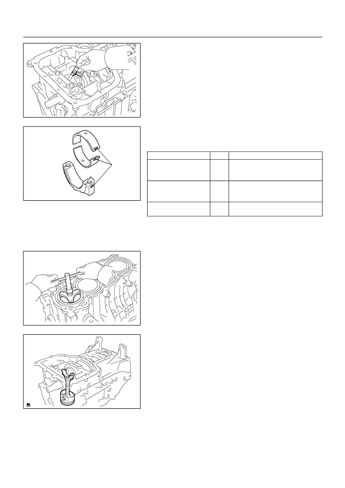
(c)
Clean the crank pin and bearing.
(d) Check the crank pin and bearing for pitting and scratches.
A65712

14-148
ENGINE MECHANICAL
- CYLINDER BLOCK ASSY (April, 2003)
(e) Lay a strip of the Plastigage across the crank pin.
Plastigage
A01159
(f)
Check that the front mark of the connecting rod cap is fac-
Front Mark
ing the correct direction.
(g) Apply a light coat of engine oil on the threads and under
the heads of the connecting rod cap bolts.
A65713
(h) Using SST, tighten the bolts in several passes by the spe-
cified torque.
SST
SST
09205-16010
Torque: 20 N m (204 kgf cm, 15 ft lbf)
A65714
(i)
Mark the front of the connecting cap bolts with paint.
(j)
Retighten the cap bolts by 90_ as shown in the illustration.
Engine
90_
(k)
Check that the crankshaft turns smoothly.
Front
Paint Mark
A65715
(l)
Remove the 2 bolts and connecting rod cap.
SST
A65712
14-149
ENGINE MECHANICAL
- CYLINDER BLOCK ASSY (April, 2003)
(m) Measure the Plastigage at its widest point.
Standard oil clearance:
0.028 to 0.060 mm (0.0011 to 0.0024 in.)
Maximum oil clearance: 0.080 mm (0.0031 in.)
NOTICE:
Remove the Plastigage completely after the measurement.
F
If the oil clearance is greater than maximum, re-
place the connecting rod bearing.
A01160
F
If necessary, grind or replace the crankshaft.
HINT:
If replacing a bearing, select a new one having the same num-
ber as marked on the connecting rod. There are 3 sizes of stan-
dard bearings, marked ”1”, ”2” and ”3” accordingly.
Item
Mark
mm (in.)
Mark
1
47.000 to 47.008 (1.8504 to 1.8507)
Connecting rod large end
2
47.009 to 47.016 (1.8507 to 1.8510)
bore diameter
3
47.017 to 47.024 (1.8511 to 1.8513)
1
1.486 to 1.490 (0.0585 to 0.0587)
Connecting rod bearing
2
1.491 to 1.494 (0.0587 to 0.0588)
thickness
A65716
3
1.495 to 1.498 (0.0589 to 0.0590)
Crankshaft pin outer diame-
-
43.992 to 44.000 (1.7320 to 1.7323)
ter
4.
REMOVE CONNECTING ROD SUB-ASSY
(a) Using a ridge reamer, remove all the carbon from the top
of the cylinder.
A01166
(b) Push the piston, connecting rod assembly and upper
bearing through the top of the cylinder block.
HINT:
F
Keep the bearing, connecting rod and cap together.
F
Arrange the piston and connecting rod assemblies in the
correct order.
A64813

14-150
ENGINE MECHANICAL
- CYLINDER BLOCK ASSY (April, 2003)
5.
REMOVE CONNECTING ROD BEARING
(a) Remove the connecting rod bearing from the connecting
rod cap.
A64814
(b) Remove the connecting rod bearing from the connecting
rod.
A64815
Piston Ring
6.
REMOVE PISTON RING SET
Expander
(a) Using a piston ring expander, remove the 2 compression
rings.
(b) Remove the 2 side rails and oil ring by hand.
A01175
7.
REMOVE W/PIN PISTON SUB-ASSY
(a) Using a small screwdriver, pry out the 2 snap rings.
A01192
(b) Heat the piston to 80 to 90_C (176 to 194_F).
A63898

14-151
ENGINE MECHANICAL
- CYLINDER BLOCK ASSY (April, 2003)
(c)
Using a plastic hammer and brass bar, lightly tap out the
piston pin, then remove the connecting rod.
HINT:
F
The piston and pin are a matched set.
F
Arrange the piston, pin, ring, connecting rod and bearings
in the correct order.
A01179
8.
REMOVE CRANKSHAFT
(a) Remove the 10 bolts.
A64817
(b) Uniformly loosen the 10 bearing cap bolts, in several
passes, in the sequence shown in the illustration.
SST
09011-38121
3
7
9
5
1
4
8
10
6
2
A64968
(c)
Using a screwdriver, remove the bearing cap by prying
the indicated portions between the cylinder block and
bearing cap.
NOTICE:
Be careful not to damage the contact surfaces of the cylin-
der block and bearing cap.
A64819

14-152
ENGINE MECHANICAL
- CYLINDER BLOCK ASSY (April, 2003)
(d) Remove the crankshaft from the cylinder block.
A64820
9.
INSPECT CRANKSHAFT THRUST CLEARANCE
(a) Using a dial indicator, measure the thrust clearance while
prying the crankshaft back and forth with a screwdriver.
Standard thrust clearance:
0.04 to 0.24 mm (0.0016 to 0.0094 in.)
Maximum thrust clearance: 0.30 mm (0.0118 in.)
F
If the thrust clearance is greater than maximum,
measure the thrust washer thickness.
A32142
F
If the thickness is not specified, replace the thrust
washer.
HINT:
Thrust washer thickness: 2.430 to 2.480 mm (0.0957 to 0.0976
in.).
10. REMOVE CRANKSHAFT THRUST WASHER UPPER
(a) Remove the 2 crankshaft thrust washers from the cylinder
block.
A64821
11. REMOVE CRANKSHAFT BEARING
(a) Remove the 5 crankshaft bearings from the cylinder
block.
NOTICE:
Arrange the main bearings and thrust washers in the cor-
rect order.
A64822

14-153
ENGINE MECHANICAL
- CYLINDER BLOCK ASSY (April, 2003)
(b) Remove the 5 crankshaft bearings from the bearing cap.
NOTICE:
Arrange the main bearings and thrust washers in the cor-
rect order.
A64823
12. REMOVE STUD BOLT
(a) Using torx socket wrench E5 and E7, remove the 9 stud
bolts.
Intake Side:
Upper Side:
Bearing Cap Lower Side:
A64969

14-154
ENGINE MECHANICAL
- CYLINDER BLOCK ASSY (April, 2003)
13. INSPECT CYLINDER BLOCK FOR FLATNESS
(a) Using a precision straight edge and feeler gauge, mea-
sure the surface contacting the cylinder head gasket for
warpage.
Maximum warpage: 0.05 mm (0.0020 in.)
If the warpage is greater than maximum, replace the cylinder
block.
A64825
14. INSPECT CYLINDER BORE
(a) Using a cylinder gauge, measure the cylinder bore diame-
ter at positions A, B and C in the thrust and axial direc-
tions.
Standard diameter:
79.000 to 79.013 mm (3.1102 to 3.1107 in.)
(b) Calculate the difference between the maximum diameter
and minimum diameter of the 6 measured values.
Difference limit: 0.10 mm (0.0039 in.)
If the difference is greater than limit, replace the cylinder block.
Thrust Direction
Axial Direction
A
10 mm (0.394 in.)
B
C
10 mm (0.394 in.)
A62802
15. INSPECT W/PIN PISTON SUB-ASSY
(a) Using a micrometer, measure the piston diameter at a
right angle to the piston pin hole, and at the piston of 25.6
mm (1.008 in.) from the piston head.
Piston diameter:
78.872 to 78.972 mm (3.1052 to 3.1091 in.)
25.6 mm (1.008 in.)
A62803

14-155
ENGINE MECHANICAL
- CYLINDER BLOCK ASSY (April, 2003)
16. INSPECT PISTON OIL CLEARANCE
(a) Subtract the piston diameter measurement from the cylinder bore diameter measurement.
Standard oil clearance: 0.065 to 0.088 mm (0.0026 to 0.0035 in.)
Maximum oil clearance: 0.088 mm (0.0035 in.)
F
If the oil clearance is greater than maximum, replace all the pistons.
F
If necessary, replace the cylinder block.
17.
INSPECT PISTON PIN OIL CLEARANCE
(a)
Using a caliper gauge, measure the piston pin bore diam-
eter.
Piston pin bore diameter:
20.006 to 20.015 mm (0.7876 to 0.7880 in.)
Mark
mm (in.)
A
20.006 to 20.009 (0.7876 to 0.7878)
B
20.010 to 20.012 (0.7878 to 0.7879)
C
20.013 to 20.015 (0.7879 to 0.7880)
A13490
(b)
Using a micrometer, measure the piston pin outer diame-
ter.
Piston pin outer diameter:
20.004 to 20.013 mm (0.7876 to 0.7879 in.)
Mark
mm (in.)
A
20.004 to 20.007 (0.7876 to 0.7877)
B
20.008 to 20.010 (0.7877 to 0.7878)
C
20.011 to 20.013 (0.7878 to 0.7879)
EM0227
(c)
Using a caliper gauge, measure the connecting rod small
end bore diameter.
Connecting rod small end bore diameter:
20.012 to 20.021 mm (0.7879 to 0.7882 in.)
Mark
mm (in.)
A
20.012 to 20.015 (0.7879 to 0.7880)
B
20.016 to 20.018 (0.7880 to 0.7881)
C
20.019 to 20.021 (0.7881 to 0.7882)
A01185

14-156
ENGINE MECHANICAL
- CYLINDER BLOCK ASSY (April, 2003)
(d)
Subtract the piston pin outer diameter measurement from
Piston:
the piston pin bore diameter measurement.
Front Mark
Standard oil clearance:
0.002 to 0.011 mm (0.0001 to 0.0004 in.)
Maximum oil clearance: 0.011 mm (0.0004 in.)
F
If the oil clearance is greater than maximum, re-
place the connecting rod.
F
If necessary, replace the w/ pin piston.
Connecting Rod:
Piston Pin
(e)
Subtract the piston pin outer diameter measurement from
Bore Diameter
Mark
the connecting rod small end bore diameter measure-
ment.
Standard oil clearance:
Front Mark
-0.001 to 0.017 mm (-0.00004 to 0.0007 in.)
Connecting Rod
Maximum oil clearance: 0.017 mm (0.0007 in.)
Small End
Bore Diameter
F
If the oil clearance is greater than maximum, re-
Mark
place the connecting rod.
F
If necessary, replace the connecting rod and w/ pin
piston.
A64970
18.
INSPECT RING GROOVE CLEARANCE
(a)
Using a feeler gauge, measure the clearance between
the new piston ring and the wall of the ring groove.
Ring groove clearance:
0.02 to 0.07 mm (0.0008 to 0.0028 in.) for No. 1 ring
0.03 to 0.07 mm (0.0012 to 0.0028 in.) for No. 2 ring
0.03 to 0.11 mm (0.0012 to 0.0043 in.) for oil ring
If the groove clearance is not as specified, replace the piston
A01171
ring.
19. INSPECT PISTON RING END GAP
(a) Using a piston, push the piston ring a little beyond the bot-
tom of the ring travel, that means 110 mm (4.33 in.) from
the top of the cylinder block.
110 mm
(4.33 in.)
A01170