Toyota Corolla (2004+). Manual - part 65

05-196
DIAGNOSTICS
- SFI SYSTEM (April, 2003)
TYPICAL ENABLING CONDITIONS
Criteria
Item
Minimum
Maximum
The monitor will run whenever the follow-
See ”List of Disable a Monitor” (On page 05-25)
ing DTCs are not present
The same as that for DTC P0442
TYPICAL MALFUNCTION THRESHOLDS
P0441
Detection Criteria
Threshold
Following conditions (a) and (b) are met:
-
(a) Fuel tank pressure is -1.6 kPa (-12 mmhg) or more at
-
the vacuum introduction start
(b) Difference between the fuel tank pressures at the vacu-
Less than 0.9 kPa (7 mmHg)
um introduction start and completion
Following conditions are met for 14 seconds
A and B
A. Difference between ”minimum fuel tank pressure before
leak check” and ”fuel tank pressure when 14seconds after
0.5 kPa or more (3.5 mmHg)
leak check”
B. Fuel tank pressure at 14 seconds after leak check
Less than - 3.7 kPa (-28 mmHg)
P0446
Detection Criteria
Threshold
Case 1: CCV stuck closed
Fuel tank pressure when the CCV is opened after an EVAP
Not changing
leak check
Case 2: VSV for pressure switching valve malfunction
Fuel tank pressure when the VSV for bypass valve is closed
Not changing
after an EVAP leak check
Case 3: VSV for EVAP stuck closed
Fuel tank pressure after the VSV for EVAP is opened and
Not changing
manifold vacuum is introduced to the fuel tank
MONITOR RESULT (MODE 06 DATA)
Conversion
Test ID
Comp ID
Description of Test Data
Description of Test Limit
Unit
Factor
Tank pressure change value dur-
Malfunction criteria for VSV for
Multiply by
$81
mmHg
ing vacuum introduction
EVAP
0.0916
Fuel tank pressure change value
Malfunction criteria for canister
Multiply by
at switching over the canister
$82
close valve and VSV for pressure
mmHg
0.0458 minus
close valve or VSV for pressure
switching valve
2.930
switching valve.
$02
Fuel tank pressure change 5 se-
Multiply by
$03
conds after the end the vacuum
Malfunction criteria for 0.040 leak
mmHg
0.0458
introduction cycle
Conditions:
F VSV for EVAP: Closed
Multiply by
$04
F CCV: Closed
Malfunction criteria for 0.020 leak
mmHg
0.0458
F VSV for bypass valve: Open
Refer to page 05-27 for the detailed information on Checking Monitor Status.

05-197
DIAGNOSTICS
- SFI SYSTEM (April, 2003)
WIRING DIAGRAM
V 4
Junction
ECM
Vapor Pressure Sensor
Connector
6
16
D
B
18
3
Y
Y
Y
Y
VC
ID2
II2
J3
J2
E3
2
21
2
L
L
ID2
E6
PTNK
1
7
28
1
BR
BR
BR F
F
BR
E2
ID2
II2
E3
J 3
B
Junction
Connector
5
AM2
Ignition Switch
6
IM
Instrument
Panel J/B
6 IG2
5
12
B-W
B-W
AM2
IL
IC
Instrument
10
Panel J/B
B-W
EA1
3
IM
3
B-R
EA1
V 2
2
IA4
VSV (Canister Closed Valve)
B-W
17
1
R-W
B
2
1
L
L
II2
E5
CCV
B-R
V 3
1
1
1
1
VSV (EVAP)
12
EVP
B
2
1
L-B
EFI
E3
2
EFI
2
5
Relay1
V 5
VSV (Vaper Pressure Sensor)
8
4
TBP
2
1
R
R
1
ID2
E6
1
MAIN
3
2
B
B
7
1
1
1A
1
1
B
B
+B
ID2
E6
Engine
B
B
Rome J/B
FL
2 4B
3 4B
and R/B
MAIN
W-B
6
1
9
EA1
B
B
II1
4B
B
Center J/B
Battery
ED
A84930
05-198
DIAGNOSTICS
- SFI SYSTEM (April, 2003)
INSPECTION PROCEDURE
HINT:
F
If DTC P0441 (Purge Flow), P0446 (VSV for CCV or VSV for Pressure switching valve), P0451, P0452
or P0453 (See page 05-242) is output with DTC P0442 or P0456 (See page 05-218), first trouble-
shoot DTC P0441, P0446, P0451, P0452 or P0453. If no malfunction is detected, troubleshoot DTC
P0442 or P0456 next.
F
Read freeze frame data using the hand-held tester or the OBD II scan tool. Freeze frame data records
the engine conditions when a malfunction is detected. When troubleshooting, it is useful for determin-
ing whether the vehicle was running or stopped, the engine was warmed up or not, the air-fuel ratio
was lean or rich, etc. at the time of the malfunction.
F
When the ENGINE RUN TIME in the freeze frame data is less than 200 seconds, carefully check the
vapor pressure sensor.
Hand-held Tester:
1
CHECK FUEL TANK CAP ASSY(CHECK THAT FUEL TANK CAP IS TOYOTA
GENUINE PARTS)
NG REPLACE TO TOYOTA GENUINE PARTS
OK
2
CHECK THAT FUEL TANK CAP IS CORRECTLY INSTALLED
NG CORRECTLY INSTALL FUEL TANK CAP
OK
3
INSPECT FUEL TANK CAP ASSY (See page 12-1)
NG REPLACE FUEL TANK CAP ASSY
OK
4
CHECK FILLER NECK FOR DAMAGE
(a) Remove the fuel tank cap.
(b) Visually check the fuel inlet pipe for damage.
(c)
Reinstall the fuel tank cap.
NG REPLACE FUEL TANK INLET PIPE SUB-ASSY
OK

05-199
DIAGNOSTICS
- SFI SYSTEM (April, 2003)
5
PERFORM ACTIVE TEST BY HAND-HELD TESTER(CHECK FOR EVAP PURGE
FLOW)
(a) Select the item ”DIAGNOSIS/ENHANCED OBD II/AC-
Air
Air
TIVE TEST” mode on the hand-held tester.
(b) Disconnect the vacuum hose of the VSV for EVAP from
the charcoal canister.
(c)
Start the engine.
(d) Select the item ”EVAP VSV (ALON)/ALL” in the ACTIVE
TEST and operate EVAP VSV (Press the right or left but-
VSV is ON
VSV is OFF
ton).
A65767
(e) When the VSV for the EVAP is operated by the hand-held
tester, check whether the disconnected hose applies suc-
tion to your finger.
Result:
VSV is ON: Disconnected hose sucks.
VSV is OFF: Disconnected hose does not suck.
(f)
Reconnect the vacuum hose.
OK Go to step 9
NG
6
CHECK VACUUM HOSES(INTAKE MANIFOLD - VSV FOR EVAP, VSV FOR EVAP -
CHARCOAL CANISTER)
(a) Check that the vacuum hose is connected correctly.
(b) Check the vacuum hose for looseness and disconnection.
(c)
Check the vacuum hose for cracks, hole, damage and blockage.
NG REPAIR OR REPLACE VACUUM HOSE
OK
7
INSPECT VSV FOR EVAP(OPERATION) (See page 12-1)
NG REPLACE VSV FOR EVAP
OK

05-200
DIAGNOSTICS
- SFI SYSTEM (April, 2003)
8
CHECK HARNESS AND CONNECTOR(EFI RELAY - VSV FOR EVAP, VSV FOR
EVAP - ECM)
(a) Check the harness and the connector between the VSV
Wire Harness Side:
for EVAP and the ECM.
V3
VSV for EVAP Connector
(1)
Disconnect the V3 VSV for EVAP connector.
(2)
Disconnect the E3 ECM connector.
(3)
Check the resistance between the wire harness
side connectors.
Standard (Check for open):
Front View
Tester Connection
Specified Condition
A52933
VSV for EVAP (V3-1) - EVP (E3-12)
Below 1 W
A51984
Standard (Check for short):
Tester Connection
Specified Condition
VSV for EVAP (V3-1) or EVP (E3-12) - Body ground
10 kW or higher
E3
(4)
Reconnect the VSV for EVAP connector.
(5)
Reconnect the ECM connector.
(b) Check the harness and the connector between the VSV
for EVAP and the EFI relay.
EVP
(1)
Disconnect the V3 VSV for EVAP connector.
(2)
Remove the EFI relay from the engine room R/B.
ECM Connector
A65743
(3)
Check the resistance between the wire harness
side connectors.
Engine Room R/B:
Standard (Check for open):
Tester Connection
Specified Condition
VSV for EVAP (V3-2) - EFI relay (3)
Below 1 W
Standard (Check for short):
Tester Connection
Specified Condition
EFI Relay
VSV for EVAP (V3-2) or EFI relay (3) - Body ground
10 kW or higher
(4)
Reconnect the VSV for EVAP connector.
(5)
Reinstall the EFI relay.
A65750
NG REPAIR OR REPLACE HARNESS OR
CONNECTOR
OK
REPLACE ECM (See page
10-11)

05-201
DIAGNOSTICS
- SFI SYSTEM (April, 2003)
9
PERFORM ACTIVE TEST BY HAND-HELD TESTER(VSV FOR CCV)
(a) Disconnect the vacuum hose of the VSV for CCV from the
F
charcoal canister.
F
(b) Start the engine.
E
E
(c)
Select the item ”DIAGNOSIS/ENHANCED OBD II/AC-
Air
Air
TIVE TEST” mode on the hand-held tester.
(d) Select the item ”CAN CTRL VSV/ALL” in the ACTIVE
TEST and operate CAN CTRL VSV (Press the right or left
button).
VSV is ON
VSV is OFF
A65768
(e) Check the VSV operation when it is operated by the
hand-held tester.
Result:
VSV is ON: Air from port E flows out through port F.
VSV is OFF: Air does not flow from port E to port F.
OK Go to step 13
NG
10
CHECK VACUUM HOSES(VSV FOR CCV - CHARCOAL CANISTER)
(a) Check that the vacuum hose is connected correctly.
(b) Check the vacuum hose for looseness and disconnection.
(c)
Check the vacuum hose for cracks, hole, damage and blockage.
NG REPAIR OR REPLACE VACUUM HOSES
OK
11
INSPECT VSV FOR CCV(OPERATION) (See page 12-6)
NG REPLACE VSV FOR CCV
OK

05-202
DIAGNOSTICS
- SFI SYSTEM (April, 2003)
12
CHECK HARNESS AND CONNECTOR(EFI RELAY - VSV FOR CCV, VSV FOR CCV
- ECM)
(a) Check the harness and connector between the VSV for
Wire Harness Side:
CCV and ECM.
VSV for CCV Connector
(1)
Disconnect the V2 VSV for CCV connector.
V2
(2)
Disconnect the E5 ECM connector.
(3)
Check the resistance between the wire harness
side connectors.
Standard (Check for open):
Front View
Tester Connection
Specified Condition
A54386
VSV for CCV (V2-1) - CCV (E5-1)
Below 1 W
Tester Connection
Specified Condition
VSV for CCV (V2-1) or CCV (E5-1) - Body ground
10 kW or higher
(4)
Reconnect the VSV for CCV connector.
E5
(5)
Reconnect the ECM connector.
(b) Check the harness and the connector between the VSV
for CCV and the EFI relay.
(1)
Disconnect the V2 VSV for CCV connector.
CCV
(2)
Remove the EFI relay from the engine room R/B.
(3)
Check the resistance between the wire harness
ECM Connector
A65744
side connectors.
Standard (Check for open):
Engine Room R/B:
Tester Connection
Specified Condition
VSV for CCV (V2-2) - EFI relay (3)
Below 1 W
Standard (Check for short):
Tester Connection
Specified Condition
VSV for CCV (V2-2) or EFI relay (3) - Body ground
10 kW or higher
EFI Relay
(4)
Reconnect the VSV for CCV connector.
(5)
Reinstall the EFI relay.
A65750
NG REPAIR OR REPLACE HARNESS OR
CONNECTOR
OK
REPLACE ECM (See page 10-11)

05-203
DIAGNOSTICS
- SFI SYSTEM (April, 2003)
13
PERFORM ACTIVE TEST BY HAND-HELD TESTER(VSV FOR PRESSURE
SWITCHING VALVE)
(a) Select the item ”DIAGNOSIS/ENHANCED OBD II/AC-
Air
Air
TIVE TEST” mode on the hand-held tester.
(b) Select the item ”TANK BYPASS VSV/ALL” in the ACTIVE
E
E
TEST and operate TANK BYPASS VSV (Press the right
or left button).
(c)
Check the VSV operation when it is operated by the
hand-held tester.
F
F
Result:
VSV is ON
VSV is OFF
A52984
VSV is ON: Air from port E flows out through port F.
VSV is OFF: Air does not flow from port E to port F.
OK Go to step 16
NG
14
INSPECT VSV FOR PRESSURE SWITCHING VALVE(OPERATION)
NG REPLACE VSV FOR PRESSURE SWITCHING
VALVE
OK

05-204
DIAGNOSTICS
- SFI SYSTEM (April, 2003)
15
CHECK HARNESS AND CONNECTOR(EFI RELAY - VSV FOR PRESSURE
SWITCHING VALVE, VSV FOR PRESSURE SWITCHING VALVE - ECM)
(a) Check the harness and the connector between the VSV
Wire Harness Side:
for pressure switching valve and the ECM.
VSV for Pressure Switching Valve
(1)
Disconnect the V5 VSV for pressure switching valve
V5
connector.
(2)
Disconnect the E6 ECM connector.
(3)
Check the resistance between the wire harness
side connectors.
Front View
Standard (Check for open):
A72890
Tester Connection
Specified Condition
VSV for pressure switching valve (V5-1) - TBP (E6-4)
Below 1 W
Standard (Check for short):
Tester Connection
Specified Condition
E6
VSV for pressure switching valve (V5-1) or TBP (E6-4)
10 kW or higher
- Body ground
(4)
Reconnect the VSV for pressure switching valve
connector.
TBP
(5)
Reconnect the ECM connector.
(b) Check the harness and the connector between the VSV
ECM Connector
A65748
for pressure switching valve and the EFI relay.
(1)
Disconnect the V5 VSV for pressure switching valve
Engine Room R/B:
connector.
(2)
Remove the EFI relay from the engine room R/B.
(3)
Check the resistance between the wire harness
side connectors.
Standard (Check for open):
EFI Relay
Tester Connection
Specified Condition
VSV for pressure switching valve (V5-2) - EFI relay (3)
Below 1 W
Standard (Check for short):
A65750
Tester Connection
Specified Condition
VSV for pressure switching valve (V5-2) or EFI relay (3)
10 kW or higher
- Body ground
(4)
Reconnect the VSV for pressure switching valve
connector.
(5)
Reinstall the EFI relay.
NG REPAIR OR REPLACE HARNESS OR
CONNECTOR
OK
REPLACE ECM (See page
10-11)

05-205
DIAGNOSTICS
- SFI SYSTEM (April, 2003)
16
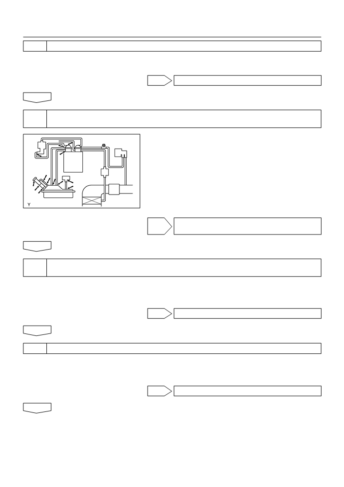
CHECK FOR EVAPORATIVE EMISSIONS LEAK(NEAR FUEL TANK)
(a) Check whether hoses close to the fuel tank have been
modified, and check if there are signs of any accident
near the fuel tank.
(1)
Check the following parts for cracks, deformation or
loose connection:
F
Fuel tank
F
Fuel tank filler pipe
F
Hoses and tubes around fuel tank
A10193
NG REPAIR OR REPLACE EVAPORATIVE
EMISSIONS LEAK PART
OK
17
CHECK VACUUM HOSES(VAPOR PRESSURE SENSOR - FUEL TANK,
CHARCOAL CANISTER - VSV FOR PRESSURE SWITCHING VALVE)
(a) Check that the vacuum hose is connected correctly.
(b) Check the vacuum hose for looseness and disconnection.
(c)
Check the vacuum hose for cracks, hole and damage.
NG REPAIR OR REPLACE VACUUM HOSE
OK
18
CHECK HOSE AND TUBE(FUEL TANK - CHARCOAL CANISTER)
(a) Check the connection between the fuel tank and fuel EVAP pipe, the fuel EVAP pipe and under-floor
fuel tube, the under-floor fuel tube and charcoal canister.
(b) Check the hose and the tube for cracks, hole and damage.
NG REPAIR OR REPLACE HOSE AND TUBE
OK
19
INSPECT ECM(VC VOLTAGE)
(a) Turn the ignition switch ON.
(b) Measure the voltage between the terminals of the E3
E3
VC (+)
ECM connector.
Standard:
Tester Connection
Specified Condition
VC (E3-18) - E2 (E3-28)
4.5 to 5.5 V
E2 (-)
ECM Connector
A65741
NG REPLACE ECM (See page 10-11)
OK

05-206
DIAGNOSTICS
- SFI SYSTEM (April, 2003)
20
INSPECT ECM(PTNK VOLTAGE)
(a) Turn the ignition switch ON.
(b) Measure the voltage between terminals of the E3 and E6
E3
E6
ECM connectors.
(1)
Disconnect the vacuum hose from the vapor pres-
sure sensor.
Standard (1):
Tester Connection
Specified Condition
E2 (-)
PTNK (+)
PTNK (E6-21) - E2 (E3-28)
2.9 to 3.7 V
A65741
NOTICE:
The vacuum applied to the vapor pressure sensor must be
TYPE A
less than 66.7 kPa (500 mmHg, 19.7 in.Hg).
Disconnect
(2)
Using the MITYVAC (Hand-held Vacuum Pump),
apply a vacuum of 4.0 kPa (30 mmHg, 1.18 in.Hg)
to the vapor pressure sensor.
Standard (2):
TYPE B
Vacuum
Tester Connection
Specified Condition
Disconnect
PTNK (E6-21) - E2 (E3-28)
0.5 V or less
Vacuum
(3)
Reconnect the vacuum hose.
A73630
OK Go to step 22
NG
21
CHECK HARNESS AND CONNECTOR(VAPOR PRESSURE SENSOR - ECM)
(a) Disconnect the V4 vapor pressure sensor connector.
Wire Harness Side:
(b) Disconnect the E3 and E6 ECM connectors.
Vapor Pressure Sensor Connector
(c)
Check the resistance between the wire harness side con-
V4
nectors.
Standard (Check for open):
Tester Connection
Specified Condition
PTNK (V4-2) - PTNK (E6-21)
GND PTNK VCC
GND (V4-1) - E2 (E3-28)
Below 1 W
Front View
VCC (V4-3) - VC (E3-18)
A72886
Standard (Check for short):
Tester Connection
Specified Condition
PTNK (V4-2) or PTNK (E6-21) - Body ground
10 kW or higher
E3
E6
VCC (V4-3) or VC (E3-18) - Body ground
(d) Reconnect the vapor pressure sensor connector.
(e) Reconnect the ECM connectors.
VC
PTNK
E2
ECM Connector
A79127
NG REPAIR OR REPLACE HARNESS OR
CONNECTOR
OK
05-207
DIAGNOSTICS
-
SFI SYSTEM (April, 2003)
REPLACE ECM (See page 10-11)
22
INSPECT FUEL TANK INLET VALVE ASSY
NG REPLACE FUEL TANK INLET VALVE ASSY
OK
23
INSPECT FUEL TANK ASSY
NG REPLACE FUEL TANK ASSY
OK
24
INSPECT CHARCOAL CANISTER ASSY(CRACKS, HOLE AND DAMAGE)
NG REPAIR OR REPLACE CHARCOAL CANISTER
ASSY
OK
REPLACE ECM (See page 10-11)
OBDII scan tool (excluding Hand-held Tester):
1
CHECK FUEL TANK CAP ASSY(CHECK THAT FUEL TANK CAP IS TOYOTA
GEHUINE PARTS)
NG REPLACE TO GENUINE PARTS
OK
2
CHECK THAT FUEL TANK CAP IS CORRECTLY INSTALLED
NG CORRECTLY INSTALL FUEL TANK CAP
OK
3
INSPECT FUEL TANK CAP ASSY (See page 12-1)
NG REPLACE FUEL TANK CAP ASSY
OK
05-208
DIAGNOSTICS
- SFI SYSTEM (April, 2003)
4
CHECK FILLER NECK FOR DAMAGE
(a) Remove the fuel tank cap.
(b) Visually check the fuel inlet pipe for damage.
NG REPLACE FUEL TANK INLET PIPE SUB-ASSY
OK
5
CHECK FOR EVAPORATIVE EMISSIONS LEAK(NEAR FUEL TANK OR CHACOAL
CANISTER)
(a) Check whether hoses close to the fuel tank have been
modified, and check if there are signs of any accident
near the fuel tank or the charcoal canister.
(1)
Check the following parts for cracks, deformation or
loose connection:
F
Fuel tank
F
Charcoal canister
F
Fuel tank filler pipe
A10193
F
Hoses and tubes around fuel tank and char-
coal canister
NG REPAIR OR REPLACE EVAPORATIVE
EMISSIONS LEAK PART
OK
6
CHECK VACUUM HOSES(VAPOR PRESSURE SENSOR - FUEL TANK,
CHARCOAL CANISTER - VSV FOR PRESSURE SWITCHING VALVE)
(a) Check that the vacuum hose is connected correctly.
(b) Check the vacuum hose for looseness and disconnection.
(c)
Check the vacuum hose for cracks, hole and damage.
NG REPAIR OR REPLACE VACUUM HOSE
OK
7
CHECK HOSE AND TUBE(FUEL TANK - CHARCOAL CANISTER)
(a) Check the connection between the fuel tank and fuel EVAP pipe, the fuel EVAP pipe and under floor
fuel tube , the under floor fuel tube and charcoal canister.
(b) Check the hose and the tube for cracks, hole and damage.
NG REPAIR OR REPLACE HOSE AND TUBE
OK

05-209
DIAGNOSTICS
- SFI SYSTEM (April, 2003)
8
CHECK VACUUM HOSES((5), (6), (7), (8) AND (9) IN FIG. 1 IN CIRCUIT
DESCRIPTION)
(a) Check that the vacuum hose is connected correctly.
(b) Check the vacuum hose for looseness and disconnection.
(c)
Check the vacuum hose for cracks, hole and damage.
NG REPAIR OR REPLACE VACUUM HOSES
OK
9
CHECK EACH VSV CONNECTOR FOR LOOSENESS AND DISCONNECTION(VSV
FOR EVAP, VSV FOR CCV, VSV FOR PRESSURE SWITCHING VALVE)
NG REPAIR OR CONNECT VSV AND SENSOR
CONNECTOR
OK
10
INSPECT CHARCOAL CANISTER ASSY(CRACKS, HOLE AND DAMAGE)
NG CHECK AND REPLACE CHARCOAL CANISTER
ASSY
OK
11
INSPECT ECM(VC VOLTAGE)
(a) Turn the ignition switch ON.
(b) Measure voltage between the terminals of the E3 ECM
E3
VC (+)
connector.
Standard:
Tester Connection
Specified Condition
VC (E3-18) - E2 (E3-28)
4.5 to 5.5 V
E2 (-)
ECM Connector
A65741
NG REPLACE ECM (See page 10-11)
OK

05-210
DIAGNOSTICS
- SFI SYSTEM (April, 2003)
12
INSPECT ECM(PTNK VOLTAGE)
(a) Turn the ignition switch ON.
(b) Measure the voltage between terminals of the E3 and E6
E3
E6
ECM connectors.
(1)
Disconnect the vacuum hose from the vapor pres-
sure sensor.
Standard (1):
Tester Connection
Specified Condition
E2 (-)
PTNK (+)
PTNK (E6-21) - E2 (E3-28)
2.9 to 3.7 V
A65741
NOTICE:
The vacuum applied to the vapor pressure sensor must be
TYPE A
less than 66.7 kPa (500 mmHg, 19.7 in.Hg).
Disconnect
(2)
Using the MITYVAC (Hand-held Vacuum Pump),
apply a vacuum of 4.0 kPa (30 mmHg, 1.18 in.Hg)
to the vapor pressure sensor.
Standard (2):
TYPE B
Vacuum
Tester Connection
Specified Condition
Disconnect
PTNK (E6-21) - E2 (E3-28)
0.5 V or less
Vacuum
(3)
Reconnect the vacuum hose from the vapor pres-
A73630
sure sensor.
OK Go to step 14
NG