Toyota Corolla (2004+). Manual - part 39

05-309
DIAGNOSTICS
- ABS WITH EBD SYSTEM (April, 2003)
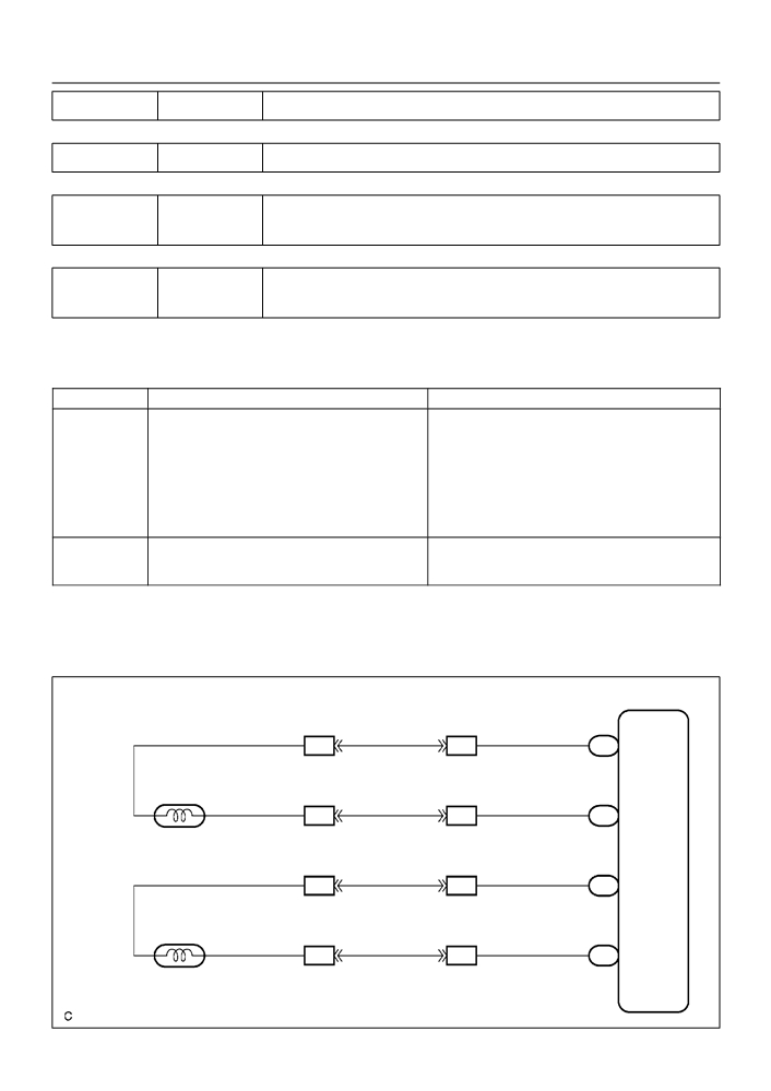
WIRING DIAGRAM
Skid Control ECU
with Actuator
13
R
S1
FL+
2
A3
ABS Speed Sensor
Front LH
26
1
G
S1
FL-
27
B
S1
FR+
2
A4
ABS Speed Sensor
Front RH
28
1
W
S1
FR-
F40884
INSPECTION PROCEDURE
HINT:
Start the inspection from step 1 in case of using the hand-held tester and start from step 2 in case of not
using the hand-held tester.
1
READ VALUE OF HAND-HELD TESTER(FRONT SPEED SENSOR)
(a) Select the DATALIST mode on the hand-held tester.
(b) Check that there is no difference between the speed value output from the speed sensor displayed
by the hand-held tester and the speed value displayed by the speedometer when driving the vehicle.
OK:
There is almost no difference in the displayed speed value.
HINT:
There is tolerance of
10 % in the speedometer indication.
OK Go to step 5
NG
05-310
DIAGNOSTICS
- ABS WITH EBD SYSTEM (April, 2003)
2
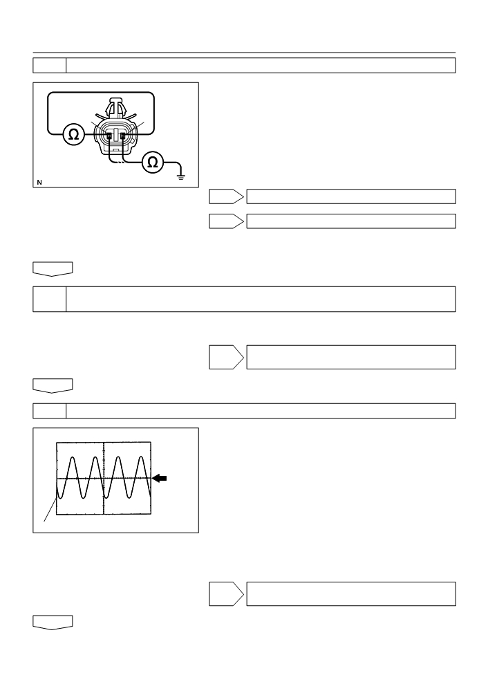
INSPECT FRONT SPEED SENSOR
(a) Remove the fender liner.
(b) Disconnect the speed sensor connector.
(c)
Measure resistance between terminals 1 and 2 of the
2
1
speed sensor connector.
OK: 0.6 - 2.5 k W or 0.9 - 1.8 k W at 20_C
(d) Measure resistance between each of terminals 1 and 2 of
speed sensor connector and body ground.
OK:
C93876
Resistance: 1 M W or higher
NG REPLACE SPEED SENSOR FRONT RH
NG REPLACE SPEED SENSOR FRONT LH
NOTICE:
Check the speed sensor signal last (See page
05-297).
OK
3
CHECK HARNESS AND CONNECTOR(FRONT SPEED SENSOR - SKID CONTROL
ECU)
(a) Check for open and short circuit in harness and connector between each front speed sensor and skid
control ECU (See page 01-30).
NG REPAIR OR REPLACE HARNESS OR
CONNECTOR
OK
4
INSPECT SPEED SENSOR AND SENSOR ROTOR SERRATIONS
(REFERENCE) INSPECTION USING OSCILLOSCOPE
Normal Signal Waveform
(a) Connect the oscilloscope to the terminal FR+ - FR- and
FL+ - FL- of the skid control ECU.
(b) Drive the vehicle at about 30 km/h (19 mph), and check
GND
the signal waveform.
HINT:
F
As the vehicle speed (wheel revolution speed) increases,
a cycle of the waveform becomes shorter and the fluctua-
2 m/s / Division
W04200
tion in the output voltage becomes greater.
1 V / Division
F
When noise is identified in the waveform on the oscillo-
scope, error signals are generated due to the speed sen-
sor rotor’s scratches, looseness or foreign matter depos-
ited on it.
OK CHECK AND REPLACE BRAKE ACTUATOR
ASSY
NG

05-311
DIAGNOSTICS
- ABS WITH EBD SYSTEM (April, 2003)
5
INSPECT FRONT SPEED SENSOR INSTALLATION
(a) Check the speed sensor installation.
OK:
The installation bolt is tightened properly and there is
no clearance between the sensor and front steering
knuckle.
Torque: 8.0 N m (82 kgf cm, 71 in. lbf)
OK
NG
BR3795
NG REPLACE SPEED SENSOR FRONT RH
NG REPLACE SPEED SENSOR FRONT LH
NOTICE:
Check the speed sensor signal last (See page
05-297).
OK
6
INSPECT SPEED SENSOR TIP
(a) Remove the front speed sensor (See page 32-44).
(b) Check the sensor tip.
OK:
No scratches or foreign objects on the sensor tip.
NG CLEAN OR REPAIR SPEED SENSOR
NOTICE:
Check the speed sensor signal last (See page
05-297).
OK
7
INSPECT SPEED SENSOR ROTOR
(a) Remove the front speed sensor rotor (See page
30-6 ).
(b) Check the sensor rotor serrations.
OK:
No scratches, missing teeth or foreign objects.
HINT:
If foreign matter is attached, remove it and after reassembling,
check the output waveform.
BR3719
NG CLEAN OR REPAIR SPEED SENSOR ROTOR
NOTICE:
Check the speed sensor signal last (See page
05-297).
OK
CHECK AND REPLACE BRAKE ACTUATOR ASSY (See page
05-306)

05-305
DIAGNOSTICS
- ABS WITH EBD SYSTEM (April, 2003)
057UB-04
LOCATION
Brake Fluid Level
Right Front Speed Sensor
Warning Switch
Brake Actuator
(Incluied Skid Control ECU)
Skid Control Sensor
Speed Sensor Rotor
Left Front Speed Sensor
Combination Meter
(ABS Warning Light)
(Brake Warning Light)
Parking Brake Switch
Stop Lamp Switch
Instrument Panel
DLC3
J/B and R/B
F42872

05-297
DIAGNOSTICS
- ABS WITH EBD SYSTEM (April, 2003)
057U9-04
PRE-CHECK
1.
DIAGNOSIS SYSTEM
(a) Release the parking brake lever.
(b) Check the warning lights.
When the ignition switch is turned ON, check that the ABS
warning light and brake warning light goes on for 3 sec.
HINT:
F
When the parking brake is applied or the level of the brake
C92542
fluid is low, the brake warning light is lit.
F
If the indicator check result is not normal, proceed to trou-
bleshooting for the ABS warning light circuit (See page
05-332 or 05-335) or brake warning light circuit (See
page 05-338).
(c)
In case of not using hand-held tester:
Tc
Check the DTC.
(1)
Using SST, it connects terminal Tc and CG of DLC3.
SST
09843-18040
(2)
Turn the ignition switch to ON.
(3)
Read the DTC from the ABS warning light on the
combination meter.
HINT:
CG
C52361
F
If not code appears, inspect the diagnostic circuit or ABS
warning light circuit (See page 05-332 or 05-335).
F
As an example, the blinking patterns for normal code and
Normal Code
codes 11 and 21 are shown on the left.
2 sec.
(4)
Codes are explained in the code table on page
0.25 sec.
05-303.
If
2 or more malfunctions are indicated at the same time, the
0.25 sec.
lowest numbered DTC will be displayed 1st.
ON
(5)
After completing the check, remove the SST from
the DLC3.
OFF
SST
09843-18040
(d) In case of using hand-held tester:
Code 11 and 21
Check the DTC.
0.5 sec.
0.5 sec.
(1)
Read the DTC by following the prompts on the tes-
1.5 sec.
ter screen.
4 sec.
2.5 sec.
HINT:
Please refer to the hand-held tester operator’s manual for fur-
ON
ther details.
(e) In case of not using hand-held tester:
OFF
Code 11
Code 21
Clear DTC.
R01346
(1)
Using SST, it connects the terminal Tc and CG of the
DLC3.
SST
09843-18040
(2)
Turn the ignition switch to ON.

05-298
DIAGNOSTICS
- ABS WITH EBD SYSTEM (April, 2003)
(3)
Clear DTC stored in ECU by depressing the brake
pedal 8 or more times whitin 5 sec.
(4)
Check that the ABS warning light shows the normal
code.
(5)
Remove the SST from the DLC3.
SST
09843-18040
HINT:
Disconnect the battey cable during repairs will not erase the
BR3890
DTC in the ECU.
(f)
In case of using hand-held tester:
Clear the DTC.
(1)
Turn the ignition switch to ON.
(2)
Operate the hand-held tester to erase the codes.
HINT:
Please refer to the hand-held tester operator’s manual for fur-
ther details.
2.
DATA LIST
HINT:
According to the DATA LIST displayed by the Hand-held tester, you can read the value of the switch, sensor,
actuator and so on without parts removal. Reading the DATA LIST as a first step of troubleshooting is one
of the method to shorten the labor time.
(a) Connect the Hand-held tester to the DLC3.
(b) Turn the ignition switch to ON.
(c)
According to the display on tester, read the ”DATA LIST”.
Measurement Item /
Item
Normal Condition
Diagnostic Note
Range (Display)
ABS motor relay / ON or
ABS MOT RELAY
OFF
Solenoid relay / ON or
SOL RELAY
OFF
ON : Brake pedal de-
Stop light switch / ON or
pressed
STOP LIGHT SW
OFF
OFF : Brake pedal re-
leased
ON : Parking brake applied
Parking brake switch / ON
PKB SW
OFF : Parking brake re-
or OFF
leased
BEFORE : No ABS opera-
ABS operation (FR) / BE-
tion (FR)
ABS OPERT FR
FORE or OPERATE
OPERATE : During ABS
operation (FR)
BEFORE : No ABS opera-
ABS operation (FL) / BE-
tion (FL)
ABS OPERT FL
FORE or OPERATE
OPERATE : During ABS
operation (FL)
BEFORE : No ABS opera-
ABS operation (RR) / BE-
tion (RR)
ABS OPERT RR
FORE or OPERATE
OPERATE : During ABS
operation (RR)
BEFORE : No ABS opera-
ABS operation (RL) / BE-
tion (RL)
ABS OPERT RL
FORE or OPERATE
OPERATE : During ABS
operation (RL)

05-299
DIAGNOSTICS
-
ABS WITH EBD SYSTEM (April, 2003)
Measurement Item /
Item
Normal Condition
Diagnostic Note
Range (Display)
Wheel speed sensor (FR)
reading / min.: 0 km/h (0
Speed indicated on
WHEEL SPD FR
Actual wheel speed
MPH, max.: 326 km/h (202
speedometer
MPH)
Wheel speed sensor (FL)
reading / min.: 0 km/h (0
Speed indicated on
WHEEL SPD FL
Actual wheel speed
MPH, max.: 326 km/h (202
speedometer
MPH)
Wheel speed sensor (RR)
reading / min.: 0 km/h (0
Speed indicated on
WHEEL SPD RR
Actual wheel speed
MPH, max.: 326 km/h (202
speedometer
MPH)
Wheel speed sensor (RL)
reading / min.: 0 km/h (0
Speed indicated on
WHEEL SPD RL
Actual wheel speed
MPH, max.: 326 km/h (202
speedometer
MPH)
ECU power supply voltage
NORMAL : 9.5 V or over
IG VOLTAGE
/ NORMAL or TOO LOW
TOO LOW : Below 9.5 V
ABS solenoid (SFRR) ON /
SFRR
OFF
ABS solenoid (SFRH) ON /
SFRH
OFF
ABS solenoid (SFLR) ON /
SFLR
OFF
ABS solenoid (SFLH) ON /
SFLH
OFF
ABS solenoid (SRRR) ON /
SRRR
OFF
ABS solenoid (SRRH) ON
SRRH
/ OFF
ABS solenoid (SRLR) ON /
SRLR
OFF
ABS solenoid (SRLH) ON /
SRLH
OFF
Air bleed support /
AIR BLD SUPPORT
Supported
SUPPORT or NOT SUP
Test mode / NORMAL or
NORMAL : Normal mode
TEST MODE
TEST
TEST : During test mode
Number of DTC recorded /
#CODES
Min.: 0, max.: 19
min.: 0, max.: 255
3.
ACTIVE TEST
HINT:
Performing the ACTIVE TEST using the Hand-held tester allows the relay, actuator and so on to operate
without parts removal. Performing the ACTIVE TEST as a first step of troubleshooting is one of the methods
to shorten the labor time.
It is possible to display the DATA LIST during the ACTIVE TEST.
(a) Connect the Hand-held tester to the DLC3.
(b) Turn the ignition switch to ON.
(c)
According to the display on tester, perform the ”ACTIVE TEST”.

05-300
DIAGNOSTICS
- ABS WITH EBD SYSTEM (April, 2003)
Item
Vehicle Condition / Test Details
Diagnostic Note
Operation of solenoid
SFRR
Turns ABS solenoid (SFRR) ON / OFF
(clicking sound) can be
heard
Operation of solenoid
SFRH
Turns ABS solenoid (SFRH) ON / OFF
(clicking sound) can be
heard
Operation of solenoid
SFLR
Turns ABS solenoid (SFLR) ON / OFF
(clicking sound) can be
heard
Operation of solenoid
SFLH
Turns ABS solenoid (SFLH) ON / OFF
(clicking sound) can be
heard
Operation of solenoid
SRRR
Turns ABS solenoid (SRRR) ON / OFF
(clicking sound) can be
heard
Operation of solenoid
SRRH
Turns ABS solenoid (SRRH) ON / OFF
(clicking sound) can be
heard
Operation of solenoid
SRLR
Turns ABS solenoid (SRLR) ON / OFF
(clicking sound) can be
heard
Operation of solenoid
SRLH
Turns ABS solenoid (SRLH) ON / OFF
(clicking sound) can be
heard
Operation of solenoid
SFRR & SFRH
Turns ABS solenoid SFRR & SFRH ON / OFF
(clicking sound) can be
heard
Operation of solenoid
SFLR & SFLH
Turns ABS solenoid SFLR & SFLH ON / OFF
(clicking sound) can be
heard
Operation of solenoid
SRRH & SRRR
Turns ABS solenoid SRH & SRR ON / OFF
(clicking sound) can be
heard
Operation of solenoid
SRLR & SRLH
Turns ABS solenoid SRLR & SRLH ON / OFF
(clicking sound) can be
heard
Operation of solenoid
SFRH & SFLH
Turns ABS solenoid SFRH & SFLH ON / OFF
(clicking sound) can be
heard
Operation of solenoid
SOL RELAY
Turns ABS solenoid relay ON / OFF
(clicking sound) can be
heard
Operation of motor can be
ABS MOT RELAY
Turns ABS motor relay ON / OFF
heard
Observe combination me-
ABS WARN LIGHT
Turns ABS warning light ON / OFF
ter
Observe combination me-
BRAKE WRN LIGHT
Turns BRAKE warning light ON / OFF
ter
4.
FREEZE FRAME DATA
(a) The vehicle (sensor) status memorized during ABS operation or at the time of error code detection can
be displayed using the hand-held tester.
(b) Only one record of freeze frame data is stored and the freeze frame data generated during ABS opera-
tion are constantly updated. Also, the number of the ignition switch’s ”ON” after the freeze frame data
is stored can be memorized up to 31 and it can be displayed.
HINT:
If the ignition switch ”ON” operation exceeds 31 times, ”31” appears on the display.

05-301
DIAGNOSTICS
- ABS WITH EBD SYSTEM (April, 2003)
(c)
If the diagnosis code abnormality occurs, the freeze frame data at the occurrence of the abnormality
is stored but the ABS actuation data is deleted.
Hand-held tester display
Measurement Item
Reference Value*
VEHICLE SPD
Vehicle speed
Speed indication of a meter
STOP LIGHT SW
Stop light switch signal
Stop light switch ON: ON, OFF: OFF
Numbers of operations of ignition switch ON after
# IG ON
0 - 31
memorizing freeze frame data
SYSTEM
Operate system
ABS operate: ABS
*: If no conditions are specifically stated for ”Idling”, it means the shift lever is at N or P position, the A/C switch
is OFF and all accessory switches are OFF.
5.
SPEED SENSOR SIGNAL CHECK
HINT:
If the ignition switch is turned from ON to ACC or LOCK during
test mode, DTC will be erased.
(a) In case of not using hand-held tester:
Check the speed sensor signal.
(1)
Turn the ignition switch to ON.
(2)
Using SST, it connects the terminal Ts and CG of
Ts
DLC3.
SST
09843-18040
(3)
Start the engine.
CG
C52361
(4)
Check that the ABS warning light blinks.
HINT:
0.13 sec.
0.13 sec.
If the ABS warning light does not blink, inspect the ABS warning
light circuit and Ts circuit
(See page 05-332 or 05-335).
ON
(5)
Drive the vehicle straight forward at the speed of 45
km/h (28 mph) or over for several seconds and
check that the ABS warning light comes off.
OFF
HINT:
BR3904
The sensor check may not be completed if the wheels spin or
the steering wheels steered during check.
(6)
Stop the vehicle.
(7)
Using SST, it connects the terminal Tc and CG of the
DLC3.
SST
09843-18040
(8)
Read the number of blinks of the ABS warning light.

05-302
DIAGNOSTICS
- ABS WITH EBD SYSTEM (April, 2003)
HINT:
F
See the list of DTC shown on the 05-303.
F
If every sensor is normal, a normal code is output (A cycle
of 0.25 sec. ON and 0.25 sec. OFF is repeated).
F
If 2 or more malfunctions are indicated at the same time,
the lowest numbered code will be displayed.
Malfunction Code (Example Code 72, 76)
7
2
7
6
ON
OFF
1.5 sec.
2.5 sec.
4 sec.
0.5 sec.
0.5 sec.
Repeat
0.5 sec. 0.5 sec.
BR3893
(9)
After performing the check, turn the ignition switch
to OFF, and remove the SST from the DLC3.
SST
09843-18040
(b) In case of using hand-held tester:
Check the speed sensor signal.
(1)
Do step (3) to (6) on the previous page.
(2)
Read the DTC by following the prompts on the tes-
ter screen.
HINT:
Please refer to the hand-held tester operator’s manual for fur-
ther details.
05-312
DIAGNOSTICS
- ABS WITH EBD SYSTEM (April, 2003)
057UF-05
DTC
C0210/33
RIGHT REAR SPEED SENSOR CIRCUIT
DTC
C0215/34
LEFT REAR SPEED SENSOR CIRCUIT
DTC
C1238/38
FOREIGN MATTER IS ATTACHED ON TIP OF
RIGHT REAR SENSOR
DTC
C1239/39
FOREIGN MATTER IS ATTACHED ON TIP OF
LEFT REAR SENSOR
CIRCUIT DESCRIPTION
Refer to DTC C0200/31, C0205/32, C1235/35, C1236/36 on page 05-308.
DTC No.
DTC Detecting Condition
Trouble Area
Detection of any of conditions 1. through 3.:
1. At vehicle speed of 10 km/h (6 mph) or more, pulses are
not input for 15 sec.
C0210/33
F Right rear and left rear speed sensor
2. Momentary interruption of the speed sensor signal oc-
C0215/34
F Each speed sensor circuit
curs at least 7 times in the time between switching the
F Speed sensor rotor
ignition switch ON and switching it OFF.
3. The condition that the speed sensor signal circuit is
open continues for 0.5 sec. or more.
At the vehicle speed of 20 km/h (12 mph) or more, the
C1238/38
F Right rear and left rear speed sensor
condition that noise is included in the speed sensor signal
C1239/39
F Speed sensor rotor
continues for 5 sec. or more.
HINT:
DTC No. C0210/33, C1238/38 is for the right rear speed sensor.
DTC No. C0215/34, C1239/39 is for the left rear speed sensor.
WIRING DIAGRAM
Skid Control ECU
with Actuator
2
2
6
W
Y
Y
BC1
IB1
S1
RL-
A19
ABS Speed Sensor
Rear LH
1
1
7
B
B
B
BC1
IB1
S1
RL+
1
2
2
4
4
W
W
W
BC1
IB1
S1
RR-
A20
ABS Speed Sensor
Rear RH
1
3
5
B
R
R
BC1
IB1
S1
RR+
1
2
F44146

05-313
DIAGNOSTICS
- ABS WITH EBD SYSTEM (April, 2003)
INSPECTION PROCEDURE
HINT:
Start the inspection from step 1 in case of using the hand-held tester and start from step 2 in case of not
using the hand-held tester.
1
READ VALUE OF HAND-HELD TESTER(SKID CONTROL SENSOR)
(a) Check that there is no difference between the speed value output from the speed sensor displayed
by the hand-held tester and the speed value displayed by the speedometer when driving the vehicle.
OK:
There is almost no difference in the displayed speed value.
HINT:
There is tolerance of ± 10 % in the speedometer indication.
OK Go to step 5
NG
2
INSPECT SKID CONTROL SENSOR
(a) Disconnect the skid control sensor connector.
(b) Measure resistance between terminals 1 and 2 of the skid
control sensor connector.
OK:
Resistance: 2.2 k Wor less
(c)
Measure resistance between each of terminals 1 and 2 of
skid control sensor connector and body ground.
OK:
F41836
Resistance: 1 M W or higher
NG REPLACE SKID CONTROL SENSOR
NOTICE:
Check the speed sensor signal last (See page
05-297).
OK
3
CHECK HARNESS AND CONNECTOR(SKID CONTROL SENSOR - SKID
CONTROL ECU)
(a) Check for open and short circuit in harness and connector between each skid control sensor and skid
control ECU (See page 01-30).
NG REPAIR OR REPLACE HARNESS OR
CONNECTOR
OK

05-314
DIAGNOSTICS
- ABS WITH EBD SYSTEM (April, 2003)
4
INSPECT SENSOR AND SENSOR ROTOR SERRATIONS
(REFERENCE) INSPECTION USING OSCILLOSCOPE
Normal Signal Waveform
(a) Connect the oscilloscope to the terminals RR+ - RR- and
RL+ - RL- of the skid control ECU.
(b) Drive the vehicle at about 30 km/h (19 mph), and check
GND
the signal waveform.
HINT:
F
As the vehicle speed (wheel revolution speed) increases,
a cycle of the waveform becomes shorter and the fluctua-
2 m/s / Division
1 V / Division
W04200
tion in the output voltage becomes greater.
F
When noise is identified in the waveform on the oscillo-
scope, error signals are generated due to the speed sen-
sor rotor’s scratches, looseness or foreign matter depos-
ited on it.
OK CHECK AND REPLACE BRAKE ACTUATOR
ASSY
NG
5
INSPECT SENSOR INSTALLATION
(a) Check the sensor installation.
OK:
There is no clearance between the sensor and rear
axle carrier.
OK
NG
F10178
NG REPLACE SKID CONTROL SENSOR
NOTICE:
Check the speed sensor signal last (See page
05-297).
OK
6
INSPECT SKID CONTROL SENSOR TIP
(a) Remove the skid control sensor (See page 32-46).
(b) Check the sensor tip.
OK:
No scratches or foreign objects on the sensor tip.
NG CLEAN OR REPAIR SKID CONTORL SENSOR
NOTICE:
Check the speed sensor signal last (See page
05-297).
OK

05-315
DIAGNOSTICS
- ABS WITH EBD SYSTEM (April, 2003)
7
INSPECT SENSOR ROTOR
(a) Check the sensor rotor serrations.
OK:
No scratches, missing teeth or foreign objects.
W04846
NG REPLACE REAR AXLE HUB & BEARING ASSY
RH
NG REPLACE REAR AXLE HUB & BEARING ASSY
LH
NOTICE:
Check the speed sensor signal last (See page
05-297).
OK
CHECK AND REPLACE BRAKE ACTUATOR ASSY (See page
05-306)
NOTICE:
Do not reuse skid control sensor.

05-307
DIAGNOSTICS
- ABS WITH EBD SYSTEM (April, 2003)
057UD-04
PROBLEM SYMPTOMS TABLE
If a normal code is displayed during the DTC check but the problem still occurs, check the circuits for each
problem symptom in the order given in the table below and proceed to the relevant troubleshooting page.
NOTICE:
When replacing Skid Control ECU, sensor or etc., turn the ignition switch to OFF.
Symptom
Suspect Area
See page
When the followings 1. to4. are all normal and the problem
is still occurring, replace the skid control ECU.
1. Check the DTC reconfirming that the normal code is
05-297
output.
ABS does not operate
2. IG power source circuit
05-324
3. Speed sensor circuit
05-308
05-312
4. Check the brake actuator with a hand-held tester.
32-40
If abnormal, check the hydraulic circuit for leakage.
When the following 1. to 4. are all normal and the problem
is still occurring, replace the skid control ECU.
1. Check the DTC reconfirming that the normal code is
05-297
output.
ABS does not operate efficiently
2. Speed sensor circuit
05-308
05-312
3. Stop light switch circuit
05-327
4. Check the brake actuator with a hand-held tester.
32-40
If abnormal, check the hydraulic circuit for leakage.
1. ABS warning light circuit
05-332
ABS warning light abnormality
05-335
2. Skid control ECU
-
When the following 1. and 2. are all normal and the problem
is still occurring, replace the skid control ECU.
DTC check cannot be done
1. ABS warning light circuit
05-332
05-335
2. Tc terminal circuit
05-341
1. Ts terminal circuit
05-343
Speed sensor signal check cannot be done
2. Skid control ECU
-