Toyota Corolla (2004+). Manual - part 40

05-341
DIAGNOSTICS
- ABS WITH EBD SYSTEM (April, 2003)
057UP-04
TC TERMINAL CIRCUIT
CIRCUIT DESCRIPTION
Connecting terminals Tc and CG of the DLC3 causes the ECU to display the DTC by flashing the ABS warn-
ing light.
WIRING DIAGRAM
D1
Skid Control ECU
DLC3
with Actuator
Center J/B
3
1
12
8
13
P-B
P-B
P-B
TC
4C
4C
IA6
S1
TC
16
21
4
W-B
W-B
CG
4B
4B
A
J6
J/C
IE
F44147

05-342
DIAGNOSTICS
- ABS WITH EBD SYSTEM (April, 2003)
INSPECTION PROCEDURE
1
INSPECT DLC3 TERMINAL VOLTAGE(Tc TERMINAL)
(a) Turn the ignition switch to ON.
DLC3
Tc
(b) Measure voltage between terminals Tc and CG of DLC3.
OK:
Voltage: 10 - 14 V
CG
C52361
OK Go to step 3
NG
2
CHECK HARNESS AND CONNECTOR(DLC3 - BODY GROUND)
(a) Check for open and short circuit in harness and connector between terminal CG of the DLC3 and body
ground (See page 01-30).
NG REPAIR OR REPLACE HARNESS OR
CONNECTOR
OK
3
CHECK HARNESS AND CONNECTOR(SKID CONTROL ECU - DLC3)
(a) Check for open and short circuit in harness and connector between terminal Tc of the skid control ECU
and DLC3 (See page 01-30).
NG REPAIR OR REPLACE HARNESS OR
CONNECTOR
OK
CHECK AND REPLACE BRAKE ACTUATOR ASSY (See page
05-306)

05-306
DIAGNOSTICS
- ABS WITH EBD SYSTEM (April, 2003)
057UC-04
TERMINALS OF ECU
S1
F07812
Symbols (Terminal No.)
Wiring Color
Condition
STD Voltage (V)
+BS (2) - GND (1, 23)
R W-B
Always
10 - 14
FL+ (13) - FL- (26)
R G
IG switch ON, slowly turn left front wheel
AC generation
RL+ (7) - RL- (6)
B Y
IG switch ON, slowly turn left rear wheel
AC generation
BRL (19) - GND (1, 23)
R W-B
IG switch ON, brake warning light ON
8 - 14
D/G (11) - GND (1, 23)
L-R W-B
IG switch ON
10 - 14
Ts (10) - GND (1,23)
GR W-B
IG switch ON
10 - 14
Tc (8) - GND (1, 23)
P-B W-B
IG switch ON
10 - 14
STP (16) - GND (1, 23)
G-W W-B
Stop light switch ON
8 - 14
+BM (24) - GND (1, 23)
L W-B
Always
10 - 14
IG1 (3) - GND (1, 23)
B-W W-B
IG switch ON
10 - 14
WA (30) - GND (1, 23)
W-R W-B
IG switch ON, ABS warning light ON
8 - 14
FR+ (27) - FR- (28)
B W
IG switch ON, slowly turn right front wheel
AC generation
RR+ (5) - RR- (4)
R W
IG switch ON, slowly turn right rear wheel
AC generation
SP1 (17) - GND (1, 23)
W-G W-B
Vehicle driving at about 20 km/h (12 mph)
AC generation
IG switch ON, parking brake switch ON
Below 1.5
PKB (12) - GND (1, 23)
R-W W-B
IG switch ON, parking brake switch OFF
10 - 14

05-294
DIAGNOSTICS
- ABS WITH EBD SYSTEM (April, 2003)
ABS WITH EBD SYSTEM (April, 2003)
057U7-04
HOW TO PROCEED WITH TROUBLESHOOTING
1
Vehicle Brought to Workshop
2
Customer Problem Analysis (See page
05-296)
3
Check and Clear DTCs and Freeze Frame Data (See page
05-297)
4
Problem Symptom Confirmation
Symptom does not occur: Go to step 5
Symptom occurs: Go to step 6
5
Symptom Simulation (See page
01-30)
6
DTC Check (See page 05-297)
There is no output: Go to step 7
There is output: Go to step 8
7
Problem Symptoms Table (See page
05-307)
Check for fluid leakage and Go to step 10
8
DTC Chart (See page 05-303)
9
Circuit Inspection (See page
05-308 - 05-343)
HINT:
When 2 or more DTC’s are recorded, and the problem is not identified, perform circuit inspection of the other
DTC’s.

05-295
DIAGNOSTICS
-
ABS WITH EBD SYSTEM (April, 2003)
10
Identification of Problem
11
Repair
12
Comfirmation Test
End
HINT:
Step 3, 6, 9, 12:
Diagnostic steps permitting the use of the hand-held tester.
Fail safe function:
When a failure occurs in the ABS system, the ABS warning light is lit and the ABS operation is prohibited.
In addition to this, when the failure which disables the EBD operation occurs, the brake warning light is lit
as well and the EBD operation is prohibited.

05-343
DIAGNOSTICS
- ABS WITH EBD SYSTEM (April, 2003)
057UQ-03
Ts Terminal Circuit
CIRCUIT DESCRIPTION
The sensor check circuit detects abnormalities in the speed sensor signal which cannot be detected with
the DTC check.
Connecting terminals Ts and CG of the DLC3 starts the check.
WIRING DIAGRAM
Skid Control ECU
D1 DLC3
with Actuator
11
10
GR
GR
TS
IA6
S1
TS
12
Center J/B
16
21
W-B
W-B
CG
4B
4B
4
A
J6
J/C
IE
F42891

05-344
DIAGNOSTICS
- ABS WITH EBD SYSTEM (April, 2003)
INSPECTION PROCEDURE
1
INSPECT DLC3 TERMINAL VOLTAGE(Ts TERMINAL)
(a) Turn the ignition switch to ON.
DLC3
Ts
(b) Measure voltage between terminals Ts and CG of DLC3.
OK:
Voltage: 10 - 14 V
CG
C52361
OK Go to step 3
NG
2
CHECK HARNESS AND CONNECTOR(DLC3 - BODY GROUND)
(a) Check for open and short circuit in harness and connector between terminal CG of the DLC3 and body
ground (See page 01-30).
NG REPAIR OR REPLACE HARNESS OR
CONNECTOR
OK
3
CHECK HARNESS AND CONNECTOR(SKID CONTROL ECU - DLC3)
(a) Check for open and short circuit in harness and connector between terminal Ts of the DLC3 and skid
control ECU (See page 01-30).
NG REPAIR OR REPLACE HARNESS OR
CONNECTOR
OK
CHECK AND REPLACE BRAKE ACTUATOR ASSY (See page
05-306)

05-619
DIAGNOSTICS
-
AUDIO SYSTEM (April, 2003)
0560A-02
RADIO BROADCAST CANNOT BE RECEIVED (BAD RECEPTION)
INSPECTION PROCEDURE
1
CHECK IF RADIO AUTO-SEARCH FUNCTIONS PROPERLY
(a) Check if the radio auto-search functions properly.
(1)
Perform the auto-search of the radio and check that it functions normally.
Standard: The radio auto-search functions properly.
OK CHECK AND REPLACE RADIO RECEIVER
ASSY
NG
2
CHECK OPTIONAL COMPONENT
(a) Check optional component (Sun shade film, telephone antenna etc.).
(1)
Check whether or not any optional component is installed, such as the sunshade film and the
telephone antenna, is installed.
Standard: Optional component is installed.
OK EFFECT FROM OPTIONAL COMPONENT
NG
3
CHECK ANTENNA FOR NOISE PRODUCTION
(a) Noise Check with Antenna
(1)
With the ignition switch in ACC, turn on the radio and choose the AM mode.
(2)
Place a tip of a screwdriver or the antenna of the antenna assembly w/ holder and check that
the noise heard from the speaker.
Standard: Noise occurs.
OK CHECK AND REPLACE RADIO RECEIVER
ASSY
NG

05-620
DIAGNOSTICS
- AUDIO SYSTEM (April, 2003)
4
INSPECT RADIO RECEIVER ASSY(ANTENNA)
(a) Preparation for Check
(1)
Remove the antenna plug of the radio receiver as-
sembly.
(b) Noise Check
(1)
With the radio receiver assembly connector con-
nected, turn the ignition switch to ACC.
(2)
Turn on the radio and choose the AM mode.
(3)
Place a flat-head screwdriver or a metal such as a
thin wire on the antenna jack of the radio receiver
assembly and check that the noise heard from the
speaker.
Standard: Noise occurs.
OK CHECK AND REPLACE RADIO RECEIVER
ASSY
E50367
NG
REPLACE AMPLIFIER ANTENNA ASSY

05-623
DIAGNOSTICS
-
AUDIO SYSTEM (April, 2003)
057P6-02
CASSETTE TAPE CANNOT BE EJECTED
WIRING DIAGRAM
See page 05-610
INSPECTION PROCEDURE
1
CHECK IF RADIO AUTO-SEARCH FUNCTIONS PROPERLY
(a) Check if the radio auto-search function properly.
(1)
Perform the auto-research of the radio and check that the operation is normal.
Standard: malfunction disappear.
NG Go to step 5
OK
2
PRESS ”EJECT” AND CHECK OPERATION
(a) Press ”EJECT” and check the operation.
(1)
Press the cassette tape EJECT switch of the radio receiver assembly for 2 sec or more and check
that the cassette tape is ejected.
Standard: The cassette tape is ejected.
NG CHECK AND REPLACE RADIO RECEIVER
ASSY
OK
3
CHECK CASSETTE TAPE
(a) Check the cassette tape.
(1)
Check that the ejected cassette tape does not have the label peeling, cassette body deformation
and others.
Standard: No fault on the cassette tape.
NG CASSETTE TAPE FAULTY
OK
4
REPLACE CASSETTE TAPE WITH ANOTHER AND RECHECK
(a) Replace the cassette tape with another and recheck.
(1)
Replace the faulty cassette tape with the normal one to see if the same trouble occurs again.
Standard: malfunction disappear.
OK CASSETTE TAPE FAULTY
NG

05-624
DIAGNOSTICS
- AUDIO SYSTEM (April, 2003)
5
INSPECT RADIO RECEIVER ASSY(+B, ACC, GND)
(a) Check that the continuity between terminals at each
+B
ACC
condition, as shown in the chart.
Standard:
Tester connection
Condition
Specified condition
GND - Body ground
Constant
Continuity
(b) Check that the voltage between terminals at each condi-
tion, as shown in the chart.
Standard:
GND
I32244
Tester connection
Condition
Specified condition
+B - GND
Constant
10 - 14 V
ACC - GND
Ignition switch ACC or ON
10 - 14 V
OK CHECK AND REPLACE RADIO RECEIVER
ASSY
NG
REPAIR OR REPLACE HARNESS OR CONNECTOR

05-621
DIAGNOSTICS
-
AUDIO SYSTEM (April, 2003)
057P5-02
CASSETTE TAPE CANNOT BE INSERTED OR PLAYED
WIRING DIAGRAM
See page 05-610
INSPECTION PROCEDURE
1
CHECK FOR ANY FOREIGN OBJECT
(a) Check for any foreign object.
(1)
Check that no foreign object or defect is detected in the cassette tape player of radio receiver
assembly.
Standard: No foreign object and defect detected.
NG REMOVE FOREIGN OBJECT
OK
2
CHECK CASSETTE TAPE
(a) Check the cassette tape.
(1)
Check that the cassette tape is a normal tape to which music or voice is recorded.
Standard: Proper cassette tape to which music or voice is recorded.
NG CASSETTE TAPE FAULTY
OK
3
REPLACE CASSETTE TAPE WITH ANOTHER AND RECHECK
(a) Replace the cassette tape with another and recheck.
(1)
Replace the faulty cassette tape with the normal one to see if the same trouble occurs again.
Standard: The function is recovered to be normal.
OK CASSETTE TAPE FAULTY
NG
4
CHECK IF RADIO AUTO-SEARCH FUNCTIONS PROPERLY
(a) Check if the radio auto-search functions properly.
(1)
Perform the auto-search of the radio and check that the operation is normal.
Standard: The operation returns to be normal.
OK CHECK AND REPLACE RADIO RECEIVER
ASSY
NG

05-622
DIAGNOSTICS
- AUDIO SYSTEM (April, 2003)
5
INSPECT RADIO RECEIVER ASSY(+B, ACC, GND)
(a) Check that the continuity between terminals at each
+B
ACC
condition, as shown in the chart.
Standard:
Tester connection
Condition
Specified condition
GND - Body ground
Constant
Continuity
(b) Check that the voltage between terminals at each condi-
tion, as shown in the chart.
Standard:
GND
I32244
Tester connection
Condition
Specified condition
+B - GND
Constant
10 - 14 V
ACC - GND
Ignition switch ACC or ON
10 - 14 V
OK CHECK AND REPLACE RADIO RECEIVER
ASSY
NG
REPAIR OR REPLACE HARNESS OR CONNECTOR
05-627
DIAGNOSTICS
- AUDIO SYSTEM (April, 2003)
057P7-02
CD CANNOT BE INSERTED OR IS EJECTED RIGHT AFTER
INSERTION
WIRING DIAGRAM
See page 05-610
INSPECTION PROCEDURE
1
CHECK IF A PROPER CD IS INSERTED
(a) Check that a proper CD is inserted.
(1)
Make sure that the CD is normal audio CD, and that there is no deformation, flaw, stain, burr and
other defects on the CD.
Standard: Normal audio CD.
Reference:
F
Translucent or different-shaped CD cannot be played.
F
CD-ROM for personal computers (with music recorded in) and recorded CD-R may not be played.
F
Playing an 3.2 in. (8-cm) CD does not require an adapter.
NG CD FAULTY
OK
2
CHECK THAT A PROPER CD IS INSERTED
(a) Check that a proper CD is inserted.
(1)
Check whether or not the CD is inserted upside down.
Standard: Not upside down.
NG SET DISC CORRECTLY
OK
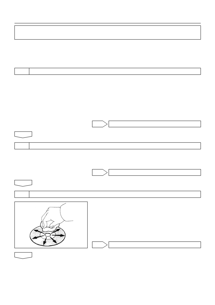
3
DISC CLEANING
(a) Disk cleaning
(1)
If the disk gets dirty, clean the disk by wiping the sur-
face from the center to outside in the radial direc-
tions with a soft cloth.
NOTICE:
Do not use a conventional record cleaner or anti-static pre-
servative.
E50013
OK DISC DIRTY
NG

05-628
DIAGNOSTICS
- AUDIO SYSTEM (April, 2003)
4
REPLACE CD WITH ANOTHER AND RECHECK
(a) Replace the CD with another and recheck.
(1)
Replace the faulty CD with the normal one to see if the same trouble occurs again.
Standard: malfunction disappear.
OK CD FAULTY
NG
5
CHECK IF RADIO AUTO-SEARCH FUNCTIONS PROPERLY
(a) Check if the radio auto-search function properly.
(1)
Perform the auto-research of the radio and check that the operation is normal.
Standard: malfunction disappear.
OK CHECK AND REPLACE RADIO RECEIVER
ASSY
NG
6
INSPECT RADIO RECEIVER ASSY(+B, ACC, GND)
(a) Check that the continuity between terminals at each
+B
ACC
condition, as shown in the chart.
Standard:
Tester connection
Condition
Specified condition
GND - Body ground
Constant
Continuity
(b) Check that the voltage between terminals at each condi-
tion, as shown in the chart.
Standard:
GND
I32244
Tester connection
Condition
Specified condition
+B - GND
Constant
10 - 14 V
ACC - GND
Ignition switch ACC or ON
10 - 14 V
OK CHECK AND REPLACE RADIO RECEIVER
ASSY
NG
REPAIR OR REPLACE HARNESS OR CONNECTOR