Toyota Corolla (2004+). Manual - part 29

41-43
MANUAL TRANSMISSION/TRANSAXLE
- MANUAL TRANSAXLE ASSY (C59)
54. INSPECT TRANSMISSION HUB SLEEVE NO.3
(a) Check the sliding condition between the transmission hub
sleeve No. 3 and transmission clutch hub No.3.
(b) Check that spline gear’s of the transmission hub sleeve
No.3 is not worn down.
C67978
(c)
Using a vernier calipers, inspect the transmission hub
sleeve No.3 and gear shift fork No.3 as shown in the il-
A
lustration.
Standard clearance:
0.3 - 0.5 mm (0.012 - 0.020 in.)
If the clearance is out of specification, replace the transmission
hub sleeve No.3 and gear shift fork No.3.
B
Clearance= (A - B)
C80375
55. INSPECT 5TH GEAR
(a) Using a caliper gauge, inspect 5th gear as shown in the
illustration.
5th gear inner diameter:
Standard inner diameter: mm (in.)
Maximum inner diameter: mm (in.)
29.915 - 29.931 (1.1778 - 1.1783)
29.931
(1.1783)
If the inner diameter exceeds the maximum, replace the 5th
gear.
C67975

41-44
MANUAL TRANSMISSION/TRANSAXLE
- MANUAL TRANSAXLE ASSY (C59)
56. INSPECT REVERSE IDLER GEAR SUB-ASSY
(a) Using a caliper gauge, inspect the reverse idler gear sub-
assy as shown in the illustration.
Reverse idler gear sub-assy inner diameter:
Standard inner diameter: mm (in.)
Maximum inner diameter: mm (in.)
18.040 - 18.058 (0.7102 - 0.7109)
18.058
(0.7109)
If the inner diameter exceeds the maximum, replace the re-
verse idler gear sub-assy.
(b) Using a micrometer, inspect the reverse idler gear shaft
as shown in the illustration.
Reverse idler gear shaft outer diameter:
Standard inner diameter: mm (in.)
Minimum outer diameter: mm (in.)
17.966 - 17.984 (0.7073 - 0.7080)
17.966
(0.7073)
If the outer diameter is below the minimum, replace the reverse
idler gear shaft.
C67846
Case
57. INSTALL OUTPUT SHAFT (MTM) COVER
Cover
(a) Coat the output shaft (MTM) cover with MP grease, install
it to the transaxle case.
NOTICE:
Install the output shaft (MTM) cover projection into the case
side hollow.
C95191
58. INSTALL OUTPUT SHAFT FRONT BEARING
(a) Coat a new output shaft front bearing with gear oil, using
SST
SST and a press, install it to the transaxle case.
SST
09950-60010 (09951-00550), 09950-70010
(09951-07150)
NOTICE:
F
Be sure to install a new bearing in the correct direc-
tion, as shown in the illustration.
C80376
F
When replacing the output shaft front bearing, re-
place the output shaft front bearing inner race along
with it.

41-45
MANUAL TRANSMISSION/TRANSAXLE
- MANUAL TRANSAXLE ASSY (C59)
59. INSTALL FRONT TRANSAXLE CASE OIL SEAL
(a) Using SST and a hammer, install a new front transaxle
case oil seal to the transaxle case.
SST
SST
09950-60010 (09951-00370), 09950-70010
(09951-07150)
Drive in depth: 15.6 - 16.0 mm (0.6142 - 0.6299 in.)
(b) Coat the lip of the front transaxle case oil seal with MP
grease.
C81790
60. INSTALL INPUT SHAFT FRONT BEARING
SST
(a) Coat a new input shaft front bearing with MP grease, us-
ing SST and a press, install it to the transaxle case.
SST
09950-60010 (09951-00420), 09950-70010
(09951-07150)
Drive in depth: 0 - 0.3 mm (0 - 0.012 in.)
C95192
61. INSTALL FR DIFFERENTIAL CASE FRONT TAPERED
ROLLER BEARING
SST
(a) Using SST and a press, install a new FR differential case
front tapered roller bearing (inner race) to the front differ-
ential case.
SST
09350-32014 (09351-32120), 09950-60010
(09951-00530)
C95110
(b) Using SST and a press, install a new FR differential case
front tapered roller bearing (outer race) with shim to the
transaxle case.
SST
SST
09950-60020 (09951-00680), 09950-70010
(09951-07150)
C80379
62. INSTALL FR DIFFERENTIAL CASE REAR TAPERED
SST
ROLLER BEARING
(a) Using SST and a press, install a new FR differential case
rear tapered roller bearing (inner race) to the front differ-
ential case.
SST
09350-32014 (09351-32120), 09950-60010
(09951-00530)
C95111

41-46
MANUAL TRANSMISSION/TRANSAXLE
- MANUAL TRANSAXLE ASSY (C59)
(b) Using SST and a press, install a new FR differential case
rear tapered roller bearing (outer race) with shim to the
SST
manual transmission case.
SST
09309-36010, 09950-60020 (09951-00710),
09950-70010 (09951-07150)
HINT:
Use a shim of the same thickness with the removed one.
C81792
63. ADJUST DIFFERENTIAL SIDE BEARING RRELOAD
(a) Coat the differential case assy with gear oil, install it to the
transaxle case.
(b) Install the manual transmission case with 16 bolts.
Torque: 29.4 N m (300 kgf cm, 22 ft lbf)
C67656
(c)
Using SST and a torque wrench, turn the differential case
SST
assy to the right and left 2 or 3 times to allow the bearings
to settle.
SST
09564-32011
C81793

41-47
MANUAL TRANSMISSION/TRANSAXLE
- MANUAL TRANSAXLE ASSY (C59)
(d) Using SST and a torque wrench, measure the preload.
SST
SST
09564-32011
Preload (at starting):
New bearing:
0.78 - 1.57 Nm (8 - 16 kgf cm, 6.9 - 13.9 in. lbf)
If the preload is out of specification, select another shim.
Shim thickness:
Mark
Thickness: mm (in.)
Mark
Thickness: mm (in.)
C81793
AA
2.10
(0.0827)
LL
2.60
(0.1024)
BB
2.15
(0.0846)
MM
2.65
(0.1043)
CC
2.20
(0.0866)
NN
2.70
(0.1063)
DD
2.25
(0.0886)
PP
2.75
(0.1083)
EE
2.30
(0.0906)
QQ
2.80
(0.1102)
FF
2.35
(0.0925)
RR
2.85
(0.1122)
GG
2.40
(0.0945)
SS
2.90
(0.1142)
HH
2.45
(0.0965)
TT
2.95
(0.1161)
JJ
2.50
(0.0984)
UU
3.00
(0.1181)
KK
2.55
(0.1004)
-
-
HINT:
The preload will change by about 0.3 - 0.4 Nm (3 - 4 kgfcm,
2.6 - 3.5 in.lbf) corresponding to a change of 0.05 mm (0.0020
in.) in shim thickness.
(e) Remove the 16 bolts and manual transmission case from
the transaxle case.
(f)
Remove the differential case assy from the transaxle
case.
64. INSTALL TRANSMISSION CASE OIL SEAL
(a) Using SST and a hammer, install a new transmission case
SST
oil seal to the manual transmission case.
SST
09316-60011 (09316-00011)
Drive in depth: 9.9
0.3 mm (0.390
0.012 in.)
(b) Coat the lip of the transmission case oil seal with MP
grease.
C80381
65. INSTALL TRANSAXLE CASE OIL SEAL
(a) Using SST and a hammer, install a new transaxle case oil
SST
seal in the transaxle case.
SST
09710-20011 (09710-06071), 09950-70010
(09951-07150)
Drive in depth: 1.9
0.3 mm (0.075
0.012 in.)
(b) Coat the lip of the transaxle case oil seal with MP grease.
C80382

41-48
MANUAL TRANSMISSION/TRANSAXLE
- MANUAL TRANSAXLE ASSY (C59)
66. INSTALL TRANSMISSION MAGNET
(a) Clean the transmission magnet, install it to the transaxle
case.
C67659
67. INSTALL BEARING LOCK PLATE
(a) Install the bearing lock plate with the bolt.
Torque: 11.3 N m (115 kgf cm, 8 ft lbf)
C67658
68. INSTALL OIL RECEIVER PIPE NO.1 (MTM)
(a) Install the oil receiver pipe No.1 (MTM) with bolt to the
manual transmission case.
Torque: 17.2 N m (175 kgf cm, 13 ft lbf)
NOTICE:
F
Prevent the oil receiver pipe No.1 (MTM) from being
deformed.
F
Install the oil receiver pipe No.1 (MTM) while placing
C68380
it against the manual transmission case, as
shown in
the illustration.
69. INSTALL OIL RECEIVER PIPE NO.2 (MTM)
(a) Install the oil receiver pipe No.2 (MTM) with bolt to the
manual transmission case.
Torque: 17.2 N m (175 kgf cm, 13 ft lbf)
NOTICE:
F
Prevent the oil receiver pipe No.2 (MTM) from being
deformed.
F
Install the oil receiver pipe No.2 (MTM) while placing
C95781
it against the manual transmission case, as
shown in
the illustration.
70. INSTALL REVERSE RESTRICT PIN ASSY
(a) Install the reverse restrict pin assy to the manual trans-
mission case.
NOTICE:
Do not set the reverse restrict pin assy in incorrect orienta-
tion.
C80383
41-49
MANUAL TRANSMISSION/TRANSAXLE
- MANUAL TRANSAXLE ASSY (C59)
(b) Using a pin punch (f 5 mm) and hammer, install the
slotted pin to the reverse restrict pin assy.
Drive in depth (A):
15.5 - 16.5 mm (0.6102 - 0.6496 in.)
(c)
Apply sealant to the reverse restrict pin plug.
Sealant:
A
Part No. 08833-00080, THREE BOND 1344, LOCTITE
242 or equivalent
C80384
(d) Using a hexagon wrench and a torque wrench, install the
reverse restrict pin plug to the manual transmission case.
Torque: 12.7 N m (130 kgf cm, 9 ft lbf)
C80385
71. INSTALL MANUAL TRANSAXLE CASE RECEIVER
(a) Install the manual transaxle case receiver with the bolt to
the transaxle case.
Torque: 11.3 N m (115 kgf cm, 8 ft lbf)
C67657
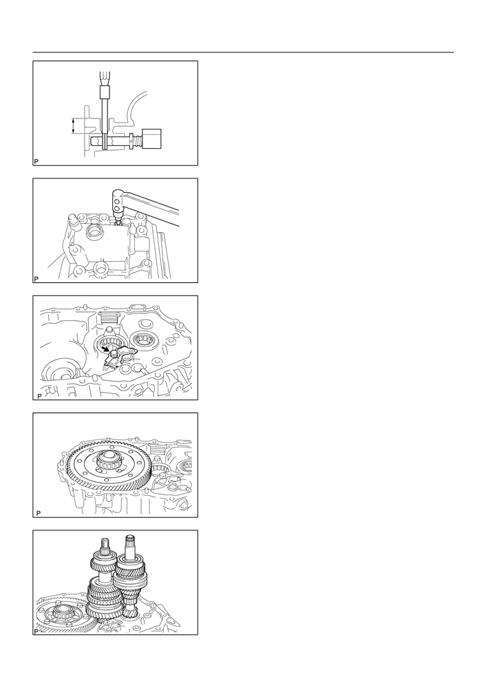
72. INSTALL DIFFERENTIAL CASE ASSY
(a) Coat the differential case tapered roller bearing with gear
oil, install the differential case assy to the transaxle case.
C67656
73. INSTALL INPUT SHAFT ASSY
(a) Coat the sliding and rotating surface of the input and out
put shafts with gear oil, install them to the transaxle case.
C80370

41-50
MANUAL TRANSMISSION/TRANSAXLE
- MANUAL TRANSAXLE ASSY (C59)
74. INSTALL REVERSE IDLER GEAR SUB-ASSY
(a) Coat the reverse idler gear sub-assy, thrust washer and
reverse idler gear shaft with gear oil, install them as
shown in the illustration.
HINT:
Align the mark on the reverse idler gear shaft with the bolt hole
shown in the illustration.
Align Alignment Mark
C80386
75. INSTALL GEAR SHIFT FORK SHAFT SUB-ASSY NO.1
Gear Shift
Fork No.2
(a) Coat the gear shift fork No.1 and gear shift fork No.2 with
gear oil, install them.
Gear Shift
Fork No.1
C80387
(b) Coat the gear shift fork shaft sub-assy No.1 with gear oil,
Gear Shift
install it.
Fork Shaft
(c)
Apply sealant to the shift fork lock bolt.
No.1
Sealant:
Part No. 08833-00080, THREE BOND 1344, LOCTITE
242 or equivalent
(d) Install the gear shift fork lock bolt.
Torque: 15.7 N m (160 kgf cm, 12 ft lbf)
C80388
(e) Using a brass bar and a hammer, install the shaft snap
ring to the gear shift fork shaft No.1.
C80389
76. INSTALL GEAR SHIFT FORK SHAFT NO.3
(a) Coat the 2 balls with MP grease, install them to the re-
verse shift fork.
(b) Install the reverse shift fork to the gear shift fork shaft
No.3.
C80450

41-51
MANUAL TRANSMISSION/TRANSAXLE
- MANUAL TRANSAXLE ASSY (C59)
(c)
Using a brass bar and a hammer, install the 2 shift fork
shaft snap rings to the gear shift fork shaft No.3.
C80391
(d) Coat the gear shift fork shaft No.3 with gear oil, install it.
C80392
77. INSTALL GEAR SHIFT FORK SHAFT NO.2
(a) Coat the gear shift head No.1 and gear shift fork shaft
No.2 with gear oil, install them.
C80362
NOTICE:
To avoid the interference of the 2 shift fork balls, lift up the
gear shift fork shaft NO.3 at the position shown in the il-
lustration.
C95193
(b) Coat the 2 shift lock bolts with sealant, install then to the
gear shift fork No.2 and gear shift head No.1.
Sealant:
Part No. 08833-00080, THREE BOND 1344, LOCTITE
242 or equivalent
Torque: 15.7 N m (160 kgf cm, 12 ft lbf)
C80361

41-52
MANUAL TRANSMISSION/TRANSAXLE
- MANUAL TRANSAXLE ASSY (C59)
78. INSTALL REVERSE SHIFT ARM BRACKET ASSY
(a) Install the reverse shift arm bracket assy with 2 bolts to the
transaxle case.
Torque: 17.2 N m (175 kgf cm, 13 ft lbf)
C80360
79. INSTALL MANUAL TRANSMISSION CASE
FIPG
(a) Apply FIPG to the manual transmission case, as shown
in the illustration.
FIPG:
Part No. 08826-00090, THREE BOND 1281 or equiva-
lent
NOTICE:
Parts must be assembled within 10 minutes of application.
C82142
Otherwise, the packing (FIPG) material must be removed
and reapplied.
(b) Coat the 13 bolts with sealant, install them to the manual
transmission case.
Sealant:
Part No. 08833-00080, THREE BOND 1344, LOCTITE
242 or equivalent
Torque: 29.4 N m (300 kgf cm, 22 ft lbf)
C80358
(c)
Coat the 3 bolts with sealant, install them to the transaxle
case.
Sealant:
Part No. 08833-00080, THREE BOND 1344, LOCTITE
242 or equivalent
Torque: 29.4 N m (300 kgf cm, 22 ft lbf)
C80357
80. INSTALL REVERSE IDLER GEAR SHAFT BOLT
(a) Coat the reverse idler gear shaft bolt with sealant, install
it with a new gasket.
Sealant:
Part No. 08833-00080, THREE BOND 1344, LOCTITE
242 or equivalent
Torque: 29.4 N m (300 kgf cm, 22 ft lbf)
C67639

41-53
MANUAL TRANSMISSION/TRANSAXLE
- MANUAL TRANSAXLE ASSY (C59)
81. INSTALL LOCK BALL ASSY NO.1
(a) Coat the lock ball assy No.1 with sealant, install it with us-
ing a hexagon wrench.
Sealant:
Part No. 08833-00080, THREE BOND 1344, LOCTITE
242 or equivalent
Torque: 39.2 N m (400 kgf cm, 29 ft lbf)
C80356
82. INSTALL SHIFT DETENT BALL
(a) Install the 2 shift detent balls, 2 springs with 2 seats to the
manual transmission case.
C68417
(b) Coat the 2 shift detent ball plugs with sealant, install them
with using a hexagon wrench.
Sealant:
Part No. 08833-00080, THREE BOND 1344, LOCTITE
242 or equivalent
Torque: 24.5 N m (250 kgf cm, 18 ft lbf)
C67634
(c)
Install the shift detent ball, spring and seat to the transaxle
case.
C80393
(d) Coat the shift detent ball plug with sealant, install it with
using a hexagon wrench.
Sealant:
Part No. 08833-00080, THREE BOND 1344, LOCTITE
242 or equivalent
Torque: 24.5 N m (250 kgf cm, 18 ft lbf)
C80354

41-54
MANUAL TRANSMISSION/TRANSAXLE
- MANUAL TRANSAXLE ASSY (C59)
83. INSTALL INPUT SHAFT REAR BEARING HOLE SNAP
RING
(a) Using a snap ring expander, install the input shaft rear
bearing hole snap ring to the input shaft.
C80352
84. INSTALL OUTPUT SHAFT REAR BEARING HOLE
SNAP RING
(a) Using a snap ring expander, install the output shaft rear
bearing hole snap ring to the output shaft.
C80351
85. INSTALL SHIFT FORK SHAFT SHAFT SNAP RING
(a) Using a brass bar and a hammer, install the shift fork shaft
shaft snap ring to the shift fork shaft No.2.
C80394
86. INSTALL BEARING RETAINER REAR (MTM)
(a) Coat the 5 bolts with sealant, install them and bearing re-
tainer rear (MTM) to the manual transmission case.
Torque: 27.4 N m (279 kgf cm, 20 ft lbf)
C80350
87. INSTALL 5TH DRIVEN GEAR
(a) Using SST, install the 5th driven gear to the output shaft.
SST
09309-12020
SST
SST
C95786

41-55
MANUAL TRANSMISSION/TRANSAXLE
- MANUAL TRANSAXLE ASSY (C59)
88. INSTALL 5TH GEAR NEEDLE ROLLER BEARING
(a) Coat the 5th gear needle roller bearing and 5th gear bear-
ing spacer with gear oil, install them to the input shaft.
C80348
89. INSTALL 5TH GEAR
(a) Coat the 5th gear with gear oil, install it to the input shaft.
C80396
90. INSTALL SYNCHRONIZER RING NO.3
(a) Coat the synchronizer ring No.3 with gear oil, install it to
the 5th gear.
Key position
C80397
91. INSTALL TRANSMISSION CLUTCH HUB NO.3
(a) Install the 3 synchromesh shifting keys and 2 synchro-
mesh shifting key springs to the transmission clutch hub
No.3.
HINT:
Do not set both openings of the shifting key springs in the same
position.
Engine
Side
C80398

41-56
MANUAL TRANSMISSION/TRANSAXLE
- MANUAL TRANSAXLE ASSY (C59)
(b) Using SST and a hammer, install the transmission clutch
hub No.3 to the input shaft.
SST
09636-20010
HINT:
SST
F
Before driving in the No.3 clutch hub assy, place the suit-
able sized wooden block on the rear side of the input
shaft, as shown in the illustration.
Key position
F
When driving it in, fix the input shaft firmly so that it is not
pushed downward. Otherwise the input shaft rear bearing
is over loaded, it might be damaged.
Wooden Block
C80399
(c)
Select a snap ring from the table below that will make the
thrust clearance of the transmission clutch hub No.3 be-
low 0.1 mm (0.0039 in.).
Snap ring thickness:
Mark
Thickness: mm (in.)
Mark
Thickness: mm (in.)
A
2.25
(0.0886)
E
2.49
(0.0980)
B
2.31
(0.0909)
F
2.55
(0.1004)
C
2.37
(0.0933)
G
2.61
(0.1028)
D
2.43
(0.0957)
-
-
C80400
(d) Using a brass bar and a hammer, install the snap ring to
the input shaft.
92. INSPECT 5TH GEAR THRUST CLEARANCE
(a) Using a dial indicator, measure the 5th gear thrust clear-
ance.
5th gear thrust clearance:
Standard clearance: mm (in.)
Maximum clearance: mm (in.)
0.10 - 0.57 (0.0039 - 0.0224)
0.57
(0.0224)
C80344

41-57
MANUAL TRANSMISSION/TRANSAXLE
- MANUAL TRANSAXLE ASSY (C59)
93. INSPECT 5TH GEAR RADIAL CLEARANCE
(a) Using a dial indicator, measure the 5th gear radial clear-
ance.
5th gear radial clearance:
Standard clearance: mm (in.)
Maximum clearance: mm (in.)
KOYO made:
KOYO made: 0.058 (0.0023)
0.015 - 0.058 (0.0006 - 0.0023)
NSK made:
NSK made: 0.056 (0.0022)
0.015 - 0.056 (0.0006 - 0.0022)
C80345
If the clearance exceed the maximum value, replace the gear,
needle roller bearing or shaft.
94. INSTALL GEAR SHIFT FORK NO.3
(a) Coat the transmission clutch hub sleeve No.3 with gear
oil, install it and gear shift fork No.3 to the transmission
clutch hub No.3.
HINT:
Do not set the transmission clutch hub No.3 in incorrect orienta-
tion.
C80401
(b) Coat the gear shift lock fork ball with sealant, install it to
the gear shift fork No.3.
Sealant:
Part No. 08833-00080, THREE BOND 1344, LOCTITE
242 or equivalent
Torque: 15.7 N m (160 kgf cm, 12 ft lbf)
C80402
95. INSTALL MANUAL TRANSMISSION OUTPUT SHAFT
REAR SET NUT
(a) Engage the gear double meshing.
(b) Install a new manual transmission output shaft rear set
nut.
Torque: 117.6 N m (1,200 kgf cm, 87 ft lbf)
C80403