Toyota Corolla (2004+). Manual - part 27

41-4
MANUAL TRANSMISSION/TRANSAXLE
- FRONT DIFFERENTIAL OIL SEAL
11. INSTALL TRANSMISSION CASE OIL SEAL
(a) Coat a new oil seal lip with MP grease.
(b) Using SST and a hammer, install the transmission case
oil seal.
SST
09554-14010, 09950-70010 (09951-07200)
Drive in depth: 9.9
0.3 mm (0.390
0.012 in.)
SST
NOTICE:
Be careful not to damage the oil seal lip.
D26133
12. INSTALL FRONT DRIVE SHAFT ASSY LH (See page 30-6)
13. INSTALL FRONT DRIVE SHAFT ASSY RH (See page 30-6)
14. INSTALL FRONT WHEELS
Torque: 103 N m (1,050 kgf cm, 76 ft lbf)
15. ADD MANUAL TRANSAXLE OIL
Oil grade: API GL-4 or GL-5
Viscosity: SAE 75 W-90
Capacity:1.9 liters (2.0 US qts, 1.7 lmp. qts)
Torque: 39.2 N m (400 kgf cm, 29 ft lbf)
0 - 5 mm
(0 - 0.20 in.)
D25304
16. INSPECT AND ADJUST MANUAL TRANSAXLE OIL (See page
41-2)
17. INSPECT AND ADJUST FRONT WHEEL ALIGNMENT (See page 26-5)
18. CHECK ABS SPEED SENSOR SIGNAL (See page 05-297)

41-62
MANUAL TRANSMISSION/TRANSAXLE
- INPUT SHAFT ASSY (C59)
INPUT SHAFT ASSY (C59)
4107G-01
COMPONENTS
3rd Gear Needle Roller Bearing
Input Shaft
3rd Gear Synchronizer Ring
Transmission Hub Sleeve No.2
Transmission Clutch Hub No.2
4th Gear Synchronizer Ring
Snap Ring
3rd Gear
4th Gear Bearing Spacer
Input Shaft Rear Radial Ball Bearing
Shifting Key Spring No.2
Shifting Key No.2
4th Gear Needle Roller Bearing
4th Gear
Snap Ring
D07720

41-63
MANUAL TRANSMISSION/TRANSAXLE
- INPUT SHAFT ASSY (C59)
4107H-01
OVERHAUL
1.
INSPECT 4TH GEAR THRUST CLEARANCE
(a) Using a feeler gauge, measure the 4th gear thrust clear-
ance.
4th gear thrust clearance:
Standard clearance: mm (in.)
Maximum clearance: mm (in.)
0.10 - 0.55 (0.0039 - 0.0217)
0.55
(0.0217)
C80557
2.
INSPECT 3RD GEAR THRUST CLEARANCE
(a) Using a dial indicator, measure the 3rd gear thrust clear-
ance.
3rd gear thrust clearance:
Standard clearance: mm (in.)
Maximum clearance: mm (in.)
0.10 - 0.35 (0.0039 - 0.0138)
0.35
(0.0138)
C67816
3.
INSPECT 4TH GEAR RADIAL CLEARANCE
(a) Using a dial indicator, measure the 4th gear radial clear-
ance.
4th gear radial clearance:
Standard clearance:
Maximum clearance:
mm (in.)
mm (in.)
0.015
- 0.058
KOYO made
0.058
(0.0023)
(0.0006
- 0.0023)
0.015
- 0.056
C80558
NSK made
0.056
(0.0022)
(0.0006
- 0.0022)
If the clearance exceeds the maximum, replace the gear,
needle roller bearing or shaft.

41-64
MANUAL TRANSMISSION/TRANSAXLE
- INPUT SHAFT ASSY (C59)
4.
INSPECT 3RD GEAR RADIAL CLEARANCE
(a) Using a dial indicator, measure the 3rd gear radial clear-
ance.
3rd gear radial clearance:
Standard clearance:
Maximum clearance:
mm (in.)
mm (in.)
0.015
- 0.058
KOYO made
0.058
(0.0023)
(0.0006
- 0.0023)
0.015
- 0.056
C67815
NSK made
0.0056
(0.0022)
(0.0006
- 0.0022)
If the clearance exceeds the maximum, replace the gear,
needle roller bearing or shaft.
5.
REMOVE 4TH GEAR
(a) Using 2 screwdrivers and a hammer, tap out the snap
ring.
HINT:
Using a waste to prevent the snap ring from being scattered.
C80559
(b) Using SST and a press, remove the input shaft radial ball
bearing rear and 4th gear from the input shaft.
SST
09950-00020
SST
NOTICE:
F
Do not tighten SST excessively.
F
Support the input shaft assy by hand so that it will not
be dropped off.
Q04983
6.
REMOVE 4TH GEAR NEEDLE ROLLER BEARING
(a) Remove the 4th gear needle roller bearing and 4th gear
bearing spacer from the input shaft.
C80560

41-65
MANUAL TRANSMISSION/TRANSAXLE
- INPUT SHAFT ASSY (C59)
7.
REMOVE 4TH GEAR SYNCHRONIZER RING
(a) Remove the 4th gear synchronizer ring from the transmis-
sion clutch hub No.2.
C80561
8.
REMOVE 3RD GEAR
(a) Using 2 screwdrivers and a hammer, tap out the snap
ring.
HINT:
Using a waste to prevent the snap ring from being scattered.
C67821
(b) Using SST and a press, remove the transmission clutch
hub No.2 and 3rd gear from the input shaft.
SST
SST
09950-00020
NOTICE:
F
Do not tighten SST excessively.
F
Support the input shaft by hand so that it will not be
dropped off.
CM0064
9.
REMOVE 3RD GEAR SYNCHRONIZER RING
(a) Remove the 3rd gear synchronizer ring from the 3rd gear.
C68515
10. REMOVE 3RD GEAR NEEDLE ROLLER BEARING
(a) Remove the 3rd gear needle roller bearing from the input
shaft.
C67823

41-66
MANUAL TRANSMISSION/TRANSAXLE
- INPUT SHAFT ASSY (C59)
11. REMOVE TRANSMISSION HUB SLEEVE NO.2
(a) Remove the transmission hub sleeve No.2, 3 synchro-
mesh shifting keys and 2 synchromesh shifting key
springs from the transmission clutch hub No.2.
HINT:
Using a waste to prevent the shifting key and shifting key spring
from being scattered.
CM0141
12. INSPECT INPUT SHAFT
(a) Using a dial indicator, check the shaft runout.
Maximum runout: 0.015 mm(0.0006 in.)
If the runout exceeds the maximum, replace the input shaft.
CM0013
(b) Using a micrometer, measure the outer diameter of the in-
put shaft journal surface.
Input shaft outer diameter:
Standard outer diameter:
Minimum outer diameter:
Part
mm (in.)
mm (in.)
24.885
- 24.900
A
24.885
(0.9797)
(0.9797
- 0.9803)
28.985
- 29.000
B
28.985
(1.1411)
(1.1411
- 1.1417)
30.985
- 31.000
C
30.985
(1.2198)
(1.2198
- 1.2204)
24.985-25.000
D
24.985
(0.9836)
(0.9836
- 0.9842)
A
B C
D
If the outer diameter is below the minimum, replace the input
shaft.
C80562
13. INSPECT 4TH GEAR
(a) Using a cylinder gauge, measure the inside diameter of
the 4th gear.
Standard inside diameter:
34.015 - 34.031 mm (1.3391 - 1.3398 in.)
Maximum inside diameter:
34.031 mm (1.3398 in.)
If the inside diameter exceeds the maximum, replace the 4th
C67826
gear.
41-67
MANUAL TRANSMISSION/TRANSAXLE
- INPUT SHAFT ASSY (C59)
14. INSPECT 3RD GEAR
(a) Using a cylinder gauge, measure the inside diameter of
the 3rd gear.
Standard inside diameter:
36.015 - 36.031 mm (1.4179 - 1.4185 in.)
Maximum inside diameter:
36.031 mm (1.4185 in.)
If the inside diameter exceeds the maximum, replace the 3rd
C67827
gear.
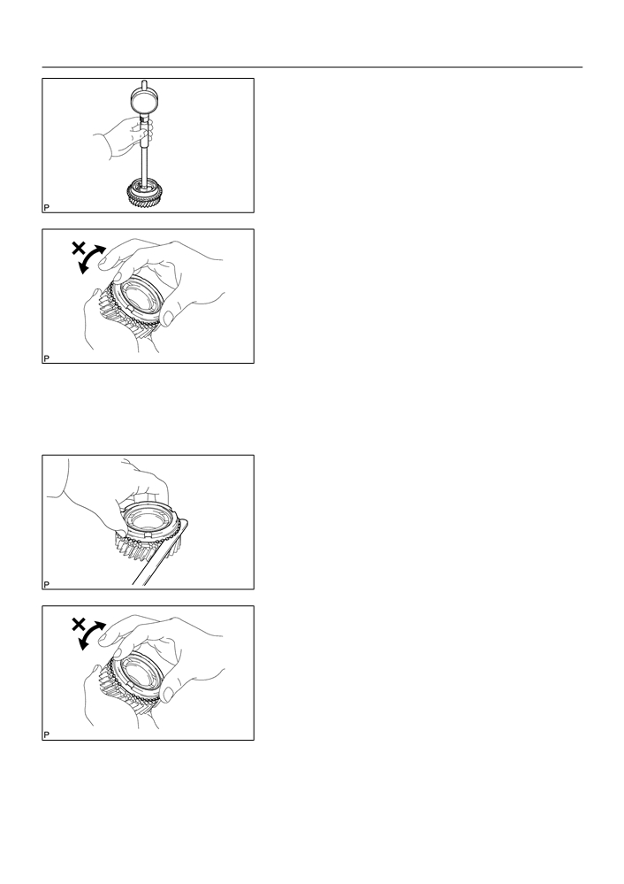
15. INSPECT 3RD GEAR SYNCHRONIZER RING
(a) Check for wear or damage.
(b) Check the braking effect of the 3rd gear synchronizer ring.
Turn the 3rd gear synchronizer ring in one direction while
pushing it to the gear cone. Check that the ring locks.
If the braking effect is insufficient, apply a small amount of the
fine lapping compound between 3rd gear synchronizer ring and
3rd gear cone. Lightly rub the 3rd gear synchronizer ring and
C80457
3rd gear cone together.
NOTICE:
Ensure the fine lapping compound is completely washed
off after rubbing.
(c)
Check again the braking effect of the synchronizer ring.
(d) Using a feeler gauge, measure the clearance between
3rd gear synchronizer ring back and 3rd gear spline end.
Minimum clearance:
0.65 mm (0.0256 in.)
If the clearance below than the minimum, replace the 3rd gear
synchronizer ring, and apply small amount of the fine lapping
compound on gear cone.
NOTICE:
C80458
Ensure the fine lapping compound is completely washed
off after rubbing.
16. INSPECT 4TH GEAR SYNCHRONIZER RING
(a) Check for wear or damage.
(b) Check the braking effect of the 4th gear synchronizer ring.
Turn the 4th gear synchronizer ring in one direction while
pushing it to the gear cone. Check that the ring locks.
If the braking effect is insufficient, apply a small amount of the
fine lapping compound between 4th gear synchronizer ring and
4th gear cone. Lightly rub the 4th gear synchronizer ring and 4th
C80457
gear cone.
NOTICE:
Ensure the fine lapping compound is completely washed
off after rubbing.

41-68
MANUAL TRANSMISSION/TRANSAXLE
- INPUT SHAFT ASSY (C59)
(c)
Using a feeler gauge, measure the clearance between
4th gear synchronizer ring back and 4th gear spline end.
Minimum clearance: 0.75 mm (0.0295 in.)
If the clearance below than the minimum, replace the 4th gear
synchronizer ring, and apply small amount of the fine lapping
compound on gear cone.
NOTICE:
Ensure the fine lapping compound is completely washed
C80458
off after rubbing.
17. INSPECT TRANSMISSION HUB SLEEVE NO.2
(a) Check the sliding condition between the transmission hub
sleeve No.2 and transmission clutch hub No.2.
(b) Check that the spline gear’s edges of the transmission
hub sleeve No.2 is not worn down.
C67843
(c)
Using a vernier caliper, inspect the transmission hub
sleeve No.2 and gear shift fork No.2 as shown in the il-
lustration.
Standard clearance:
0.15 - 0.35 mm (0.0059 - 0.0137 in.)
If the clearance is out of specification, replace the transmission
hub sleeve No.2 and gear shift fork No.2.
A
B
Clearance= (B-A)
C67842
18. INSTALL TRANSMISSION HUB SLEEVE NO.2
(a) Coat the transmission hub sleeve No.2 with gear oil,
install it to the transmission clutch hub No.2.
NOTICE:
Engine
Do not set the transmission clutch hub sleeve No.2 and the
Side
transmission clutch hub No.2 in incorrect orientation.
D02999

41-69
MANUAL TRANSMISSION/TRANSAXLE
- INPUT SHAFT ASSY (C59)
(b) Install the 2 synchromesh key springs with 3 synchro-
mesh shifting keys to the transmission clutch hub No.2.
HINT:
Do not set the both openings of the shifting key springs in the
same position.
19. INSTALL 3RD GEAR NEEDLE ROLLER BEARING
(a) Coat the 3rd gear needle roller bearing with gear oil,
install it to the input shaft.
C67823
20. INSTALL 3RD GEAR
(a) Coat the 3rd gear with gear oil, install it to the input shaft.
C67834
21. INSTALL 3RD GEAR SYNCHRONIZER RING
Key position
(a) Coat the 3rd gear synchronizer ring with gear oil, install
it to the 3rd gear.
C80463
22. INSTALL TRANSMISSION CLUTCH HUB NO.2
(a) Using SST and a press, install the transmission clutch
hub No.2 to the input shaft.
SST
09316-60011 (09316-00021)
SST
C80563

41-70
MANUAL TRANSMISSION/TRANSAXLE
- INPUT SHAFT ASSY (C59)
(b) Select a snap ring from the table below that will make the
thrust clearance of the transmission clutch hub No.2 be-
low 0.1 mm (0.0039 in.).
Snap ring thickness:
Mark
Thickness: mm (in.)
Mark
Thickness: mm (in.)
0
2.30
(0.0906)
3
2.48
(0.0976)
1
2.36
(0.0929)
4
2.54
(0.1000)
2
2.42
(0.0953)
5
2.60
(0.1024)
C67837
(c)
Using a brass bar and a hammer, tap in the snap ring.
NOTICE:
Take care not to damage the journal surface of the input
shaft.
23. INSTALL 4TH GEAR SYNCHRONIZER RING
(a) Coat the 4th gear synchronizer ring with gear oil, install it
to the transmission clutch hub No.2.
Key position
C80464
24. INSTALL 4TH GEAR NEEDLE ROLLER BEARING
(a) Coat the 4th gear needle roller bearing and 4th gear bear-
ing spacer with gear oil, install them to the input shaft.
C80560
25. INSTALL 4TH GEAR
(a) Coat the 4th gear with gear oil, install it to the input shaft.
C80564

41-71
MANUAL TRANSMISSION/TRANSAXLE
- INPUT SHAFT ASSY (C59)
26. INSTALL INPUT SHAFT REAR RADIAL BALL
BEARING
SST
(a) Using SST and a press, install the input shaft rear radial
ball bearing to the input shaft.
SST
09636-20010
C80565
(b) Select a snap ring from the table below that will make the
thrust clearance of the input shaft rear radial ball bearing
below 0.1 mm (0.0039 in.).
Snap ring thickness:
Mark
Thickness: mm (in.)
Mark
Thickness: mm (in.)
0
2.29
(0.0901)
3
2.47
(0.0972)
1
2.35
(0.0925)
4
2.53
(0.0996)
2
2.41
(0.0948)
5
2.59
(0.1019)
C80566
(c)
Using a brass bar and a hammer, tap in the snap ring.
NOTICE:
Take care not to damage the journal surface of the snap
ring.
27. INSPECT 3RD GEAR RADIAL CLEARANCE
(a) Using a dial indicator, measure the 3rd gear radial clear-
ance.
3rd gear radial clearance:
Standard clearance:
Maximum clearance:
mm (in.)
mm (in.)
0.015
- 0.058
KOYO made
0.058
(0.0023)
(0.0006
- 0.0023)
0.015
- 0.056
C67815
NSK made
0.056
(0.0022)
(0.0006
- 0.0022)
If the clearance exceeds the maximum, replace the gear,
needle roller bearing or shaft.

41-72
MANUAL TRANSMISSION/TRANSAXLE
- INPUT SHAFT ASSY (C59)
28. INSPECT 4TH GEAR RADIAL CLEARANCE
(a) Using a dial indicator, measure the 4th gear radial clear-
ance.
4th gear radial clearance:
Standard clearance:
Maximum clearance:
mm (in.)
mm (in.)
0.015
- 0.058
KOYO made
0.058
(0.0023)
(0.0006
- 0.0023)
0.015
- 0.056
C80558
NSK made
0.056
(0.0022)
(0.0006
- 0.0022)
If the clearance exceeds the maximum, replace the gear,
needle roller bearing or shaft.
29. INSPECT 3RD GEAR THRUST CLEARANCE
(a) Using a dial indicator, measure the 3rd gear thrust clear-
ance.
3rd gear thrust clearance:
Standard clearance: mm (in.)
Maximum clearance: mm (in.)
0.10 - 0.35 (0.0039 - 0.0138)
0.35
(0.0138)
C67816
30. INSPECT 4TH GEAR THRUST CLEARANCE
(a) Using a feeler gauge, measure the 4th gear thrust clear-
ance.
4th gear thrust clearance:
Standard clearance: mm (in.)
Maximum clearance: mm (in.)
0.10 - 0.55 (0.0039 - 0.0217)
0.55
(0.0217)
C80557

41-25
MANUAL TRANSMISSION/TRANSAXLE
- MANUAL TRANSAXLE ASSY (C59)
MANUAL TRANSAXLE ASSY (C59)
4107E-01
COMPONENTS
w/ ABS:
w/o ABS:
11.3 (115, 8)
Speedometer Sensor
11.3 (115, 8)
Speedometer Driven
Hole Cover Sub-assy
Clutch Release
Clip
Bearing Clip
f O-Ring
f O-Ring
Clutch Release
Speedometer
Fork Sub-assy
Driven (MTM)
Gear Sub-assy
Clutch Release
f
Transaxle Case
Floor Shift Control
Bearing Assy
Oil Seal
29.4 (300, 22)
Lever Housing Support Bracket
11.3 (115, 8)
Release
Manual Transaxle
Fork Support
Case Receiver
36.8 (375, 25)
11.3 (115, 8)
Shim
Clutch Release
Fork Boot
f
FR Differential Case Front
Transaxle Case
Transmission
Tapered Roller Bearing
Magnet
Output Shaft
(MTM) Cover
Front Transaxle
f
Output Shaft
Case Oil Seal
Front Bearing
f
Input Shaft
Bearing Lock Plate
Front Bearing
11.3 (115, 8)
Shim
fFR Differential
Differential Case Assy
Case Rear Tapered
Roller Bearing
f Transmission Case Oil Seal
Nm (kgfcm, ftlbf)
: Specified torque
f Non-reusable part
Apply MP grease
C95305

41-26
MANUAL TRANSMISSION/TRANSAXLE
- MANUAL TRANSAXLE ASSY (C59)
_ Shift Detent Ball Plug
24.5 (250, 18)
Gear Shift Fork No.1
Reverse Shift Arm
Seat
Reverse
Bracket Assy
Spring
Shift Fork
_
15.7 (160, 12)
17.2 (175, 13)
Shift Detent Ball
Snap Ring
Gear Shift Fork Shaft
Snap Ring
Sub-assy No.1
Snap
_ Shift Detent Ball Plug
Ring
24.5 (250, 18)
Seat
Reverse Idler
Spring
Thrust Washer
Gear Sub-assy
Gear Shift
Shift Detent Ball
Ball
Fork Shaft No.3
_
15.7 (160, 12)
Shift
Seat
Detent
Ball
Spring
Gear Shift Fork No.3
Reverse Idler
Gear Shaft
_ Shift Detent Ball Plug
f Gasket
24.5 (250, 18)
Gear Shift
_ Reverse Idler Gear
Fork Shaft No.2
_
15.7 (160, 12)
Shaft Bolt
29.4 (300, 22)
Snap Ring
Gear Shift Head No.1
_
15.7 (160, 12)
Output Shaft
Output Shaft Assy
Rear Bearing Hole
Gear Shift Fork No.2
Snap Ring
5th Driven Gear
f Manual Transmission
Input Shaft Assy
Output Shaft Rear Set Nut
117.6 (1,200, 87)
Input Shaft Rear
5th Gear Bearing Spacer
Bearing Hole Snap Ring
5th Gear
Synchromesh Shifting Key
Bearing Retainer Rear (MTM)
Synchromesh Shifting
_
27.4 (279, 20)
x5
Key Spring
5th Gear Needle Roller Bearing
Nm (kgfcm, ftlbf)
: Specified torque
Input Shaft Snap Ring
f Non-reusable part
_ Precoated part
Transmission Clutch Hub No.3
Z18280

41-27
MANUAL TRANSMISSION/TRANSAXLE
- MANUAL TRANSAXLE ASSY (C59)
19.6 (200, 14)
Shift & Select Lever Shaft Assy
Back Up Lamp Switch
_
40.2 (410, 30)
Lock Ball Assy No.1
_
17.2 (175, 13)
_
29.4 (300, 22)
Oil Receiver Pipe No.2
_
19.6 (200, 14)
(MTM)
24.5 (250, 18)
f Gasket
Control Shift
Reverse Restrict Pin Plug
f Gasket
Lever Bush
_
12.7 (130, 9)
Slotted Pin
Lock Ball Assy No.1
_
39.2 (400, 29)
Reverse
Restrict Pin Assy
Selecting Bellcrank Assy
Oil Receiver Pipe No. 1 (MTM)
Manual Transmission Case
17.2 (175, 13)
f Gasket
Manual Transmission
x13
Case Cover Sub-assy
Manual Transmission Filler Plug
39.2 (400, 29)
29.4 (300, 22)
18.1 (185, 14)
f Gasket
x9
Drain (MTM) Plug Sub-assy
39.2 (400, 29)
Nm (kgfcm, ftlbf)
: Specified torque
f Non-reusable part
_ Precoated part
Apply MP grease
D12108