Toyota Corolla (2004+). Manual - part 26
41-88
MANUAL TRANSMISSION/TRANSAXLE
- DIFFERENTIAL CASE ASSY (C59)
8.
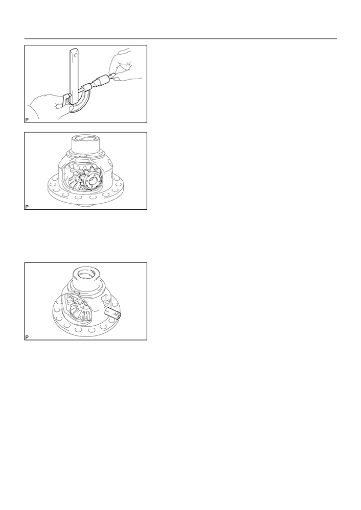
INSPECT FRONT DIFFERENTIAL PINION SHAFT
NO.1
(a) Using a micrometer, measure the the outer diameter of
the front differential pinion shaft No.1.
Minimum outer diameter: 16.982 mm (0.6686 in.)
If the outer diameter is less than the minimum, replace the front
differential pinion shaft No.1.
C68518
9.
INSTALL FRONT DIFFERENTIAL SIDE GEAR
(a) Coat the sliding and rotating surface of the 2 front differ-
ential side gears with MP grease.
(b) Install the 2 front differential side gear thrust washers to
the 2 front differential side gear.
HINT:
Install the front differential side gear thrust washer that has the
same thickness as the removed one.
C83566
(c)
Install the 2 front differential side gears, 2 front differential
pinions and 2 front differential side gear thrust washers to
the front differential case.
HINT:
Turning the front differential pinion, install the 2 front differential
pinions with front differential case.
10. INSTALL FRONT DIFFERENTIAL PINION SHAFT NO.1
(a) Coat the rotating surface of the front differential pinion
shaft No.1 with gear oil.
(b) Install the front differential pinion shaft No.1 to the front
differential case so that the hole for the front differential
pinion shaft straight pin is aligned with the hole in the front
differential case.
C83565
41-89
MANUAL TRANSMISSION/TRANSAXLE
- DIFFERENTIAL CASE ASSY (C59)
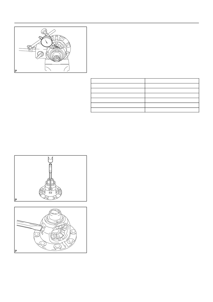
11. ADJUST FRONT DIFFERENTIAL SIDE GEAR
BACKLASH
(a) Fixing the front differential pinion to the front differential
case side. Using a dial indicator, measure the front differ-
ential side gear backlash.
Standard backlash:
0.05 - 0.20 mm (0.0020 - 0.0079 in.)
If the backlash is out of specification, replace the side gear
C67989
thrust washer.
Thrust washer thickness:
Part No.
Thickness: mm (in.)
41361 - 22140
0.95
(0.0374)
41361 - 22020
1.00
(0.0394)
41361 - 22150
1.05
(0.0413)
41361 - 22030
1.10
(0.0433)
41361 - 22160
1.15
(0.0453)
41361 - 22040
1.20
(0.0472)
HINT:
F
Because the thrust washer does not have any identifica-
tion mark, measure the front thickness with a micrometer
to select a proper thrust washer.
F
Select washers that has the same thickness as both the
right and left.
12. INSTALL FRONT DIFFERENTIAL PINION SHAFT
STRAIGHT PIN
(a) Using a pin punch (f 3 mm) and a hammer, install the front
differential pinion shaft straight pin to the front differential
case.
C67990
(b) Using a chisel and a hammer, stake the front case hole.
C67991

41-90
MANUAL TRANSMISSION/TRANSAXLE
- DIFFERENTIAL CASE ASSY (C59)
90 - 110_C (194.0 - 230.0_F)
13. INSTALL FRONT DIFFERENTIAL RING GEAR
(a) Using a heater, heat the front differential ring gear to 90
- 110_C (194.0 - 230.0_F)
(b) Clean the contact surface of the front differential case.
C94319
(c)
Align the both matchmarks, quickly install the 8 bolts with
Matchmarks
the front differential ring gear to the front differential case.
Torque: 77.4 N m (789 kgf cm, 57 ft lbf)
C94318
14. INSTALL SPEEDOMETER DRIVE (MTM) GEAR
(a) Install the speedometer drive (MTM) gear to the front dif-
ferential case.
C67982
41-85
MANUAL TRANSMISSION/TRANSAXLE
- DIFFERENTIAL CASE ASSY (C59)
DIFFERENTIAL CASE ASSY (C59)
4107K-01
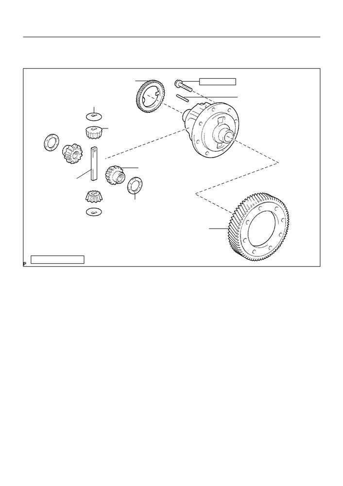
COMPONENTS
Speedometer Drive
77.4 (789, 57)
(MTM) Gear
x 8
Front Differential
Front Differential
Pinion Thrust Washer
Pinion Shaft Straight Pin
Front Differential Pinion
Front Differential Side Gear
Front Differential
Pinion Shaft No.1
Front Differential Side Gear
Thrust Washer
Front Differential Ring Gear
Nm (kgfcm, ftlbf)
: Specified torque
C95304

41-12
MANUAL TRANSMISSION/TRANSAXLE
- FLOOR SHIFT CABLE TRANSMISSION CONTROL
SELECT
FLOOR SHIFT CABLE TRANSMISSION CONTROL SELECT
41079-02
REPLACEMENT
HINT:
COMPONENTS: See page 41-5
1.
REMOVE AIR CONDITIONER UNIT ASSY (See page 55-17)
HINT:
Refer to the manuals for removal of the air conditioner unit assy.
2.
SEPARATE AIR BAG SENSOR ASSY CENTER
(a) Remove the 3 bolts, separate the airbag sensor assy center.
3.
REMOVE EXHAUST PIPE ASSY (See page 15-2)
4.
REMOVE FRONT FLOOR HEAT INSULATOR NO.1
(a) Remove the 3 nuts and heat insulator No.1.
5.
REMOVE FLOOR SHIFT CABLE TRANSMISSION
CONTROL SELECT
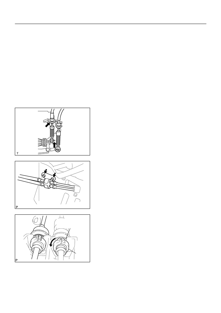
(a) Remove the clip and washer, separate the top of the se-
lect cable from the transaxle.
(b) Remove the clip, separate the select cable from the con-
trol cable bracket.
D26968
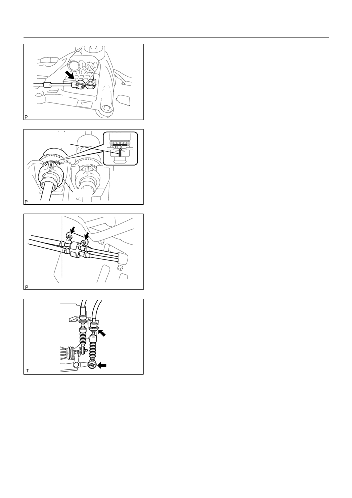
(c)
Remove the 2 nuts and clamp.
B53753
(d) Using a screwdriver, release the cable outer spring.
(e) Turn the lock, separate the select cable from the shift le-
ver retainer.
Cable Outer
Spring
Lock
D26975

MANUAL TRANSMISSION/TRANSAXLE
- FLOOR SHIFT CABLE TRANSMISSION CONTROL
41-13
SELECT
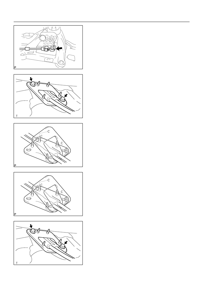
(f)
Separate the end of the select cable from the shift lever
assy.
D26976
(g) Remove the 2 bolts and retainer from the floor.
(h) Pull out the control cable assy from the floor.
D26966
(i)
Remove the retainer from the grommet.
(j)
Remove the select cable from the grommet.
B53750
6.
INSTALL FLOOR SHIFT CABLE TRANSMISSION
CONTROL SELECT
(a) Install the select cable to the grommet.
(b) Install the retainer to the grommet.
NOTICE:
Fit 4 projections of the grommet into 4 holes of the retainer.
B53750
(c)
Install the control cable assy with the 2 bolts.
Torque: 5.0 N m (51 kgf cm, 44 in. lbf)
D26966
41-14
MANUAL TRANSMISSION/TRANSAXLE
- FLOOR SHIFT CABLE TRANSMISSION CONTROL
SELECT
(d) Connect the end of the select cable to the shift lever assy.
D26976
(e) Connect the select cable to the retainer of shift lever assy,
Cable Outer
turn the lock.
Spring
NOTICE:
The projecting part of the lock should face upward when
the select cable is installed.
(f)
Install the cable outer spring to the lock.
NOTICE:
Lock
Make sure that after installation the cable outer spring is
D26916
moved to the place shown in the illustration.
(g) Install the clamp with the 2 nuts.
Torque: 5.0 N m (51 kgf cm, 44 in. lbf)
B53753
(h) Connect the select cable to the control cable bracket,
install a new clip.
(i)
Connect the select cable to the transaxle, install the
washer and clip.
D26968
7.
INSTALL FRONT FLOOR HEAT INSULATOR NO.1
(a) Install the heat insulator No.1 with the 3 nuts.
8.
INSTALL EXHAUST PIPE ASSY (See page 15-2)
9.
CONNECT AIR BAG SENSOR ASSY CENTER
(a) Install the airbag sensor assy center with the 3 bolts.
Torque: 17.5 N m (178 kgf cm, 13 ft lbf)
10. INSPECT SRS WARNING LIGHT (See page 05-424)
MANUAL TRANSMISSION/TRANSAXLE
- FLOOR SHIFT CABLE TRANSMISSION CONTROL
41-9
SHIFT
FLOOR SHIFT CABLE TRANSMISSION CONTROL SHIFT
41078-02
REPLACEMENT
HINT:
COMPONENTS: See page 41-5
1.
REMOVE AIR CONDITIONER UNIT ASSY (See page 55-17)
HINT:
Refer to the manuals for removal of the air conditioner unit assy.
2.
SEPARATE AIR BAG SENSOR ASSY CENTER
(a) Remove the 3 bolts, separate the airbag sensor assy center.
3.
REMOVE EXHAUST PIPE ASSY (See page 15-2)
4.
REMOVE FRONT FLOOR HEAT INSULATOR NO.1
(a) Remove the 3 nuts and heat insulator No.1.
5.
REMOVE FLOOR SHIFT CABLE TRANSMISSION
CONTROL SHIFT
(a) Remove the clip and washer, separate the top of the shift
cable from the transaxle.
(b) Remove the clip, separate the shift cable from the control
cable bracket.
D26696
(c)
Remove the 2 nuts and clamp.
B53753
(d) Using a screwdriver, release the cable outer spring.
Cable Outer
(e) Turn the lock, separate the shift cable from the shift lever
Spring
retainer.
Lock
D26973
41-10
MANUAL TRANSMISSION/TRANSAXLE
- FLOOR SHIFT CABLE TRANSMISSION CONTROL
SHIFT
(f)
Separate the end of the shift cable from the shift lever
assy.
D26974
(g) Remove the 2 bolts and retainer from the floor.
(h) Pull out the control cable assy from the floor.
D26966
(i)
Remove the retainer from the grommet.
B53750
6.
INSTALL FLOOR SHIFT CABLE TRANSMISSION
CONTROL SHIFT
(a) Put the control cable assy through the floor hole and re-
tainer.
(b) Install the retainer to the grommet.
NOTICE:
Fit 4 projections of the grommet into 4 holes of the retainer.
B53750
(c)
Install the control cable assy with the 2 bolts.
Torque: 5.0 N m (51 kgf cm, 44 in. lbf)
D26966

MANUAL TRANSMISSION/TRANSAXLE
- FLOOR SHIFT CABLE TRANSMISSION CONTROL
41-11
SHIFT
(d) Connect the end of the shift cable to the shift lever assy.
D26974
(e) Connect the shift cable to the retainer of shift lever assy,
Cable Outer
turn the lock.
Spring
NOTICE:
The projecting part of the lock should face upward when
the shift cable is installed.
(f)
Install the cable outer spring to the lock.
NOTICE:
Lock
Make sure that after installation the cable outer spring is
D26915
moved to the place shown in the illustration.
(g) Install the clamp with the 2 nuts.
Torque: 5.0 N m (51 kgf cm, 44 in. lbf)
B53753
(h) Connect the shift cable to the control cable bracket, install
a new clip.
(i)
Connect the shift cable to the transaxle, install the washer
and clip.
D26696
7.
INSTALL FRONT FLOOR HEAT INSULATOR NO.1
(a) Install the heat insulator No.1 with the 3 nuts.
Torque: 5.5 N m (56 kgf cm, 49 in. lbf)
8.
INSTALL EXHAUST PIPE ASSY (See page 15-2)
9.
CONNECT AIR BAG SENSOR ASSY CENTER
(a) Install the airbag sensor assy center with the 3 bolts.
Torque: 17.5 N m (178 kgf cm, 13 ft lbf)
10. INSPECT SRS WARNING LIGHT (See page 05-424)
41-5
MANUAL TRANSMISSION/TRANSAXLE
- FLOOR SHIFT SHIFT LEVER ASSY
FLOOR SHIFT SHIFT LEVER ASSY
4107A-01
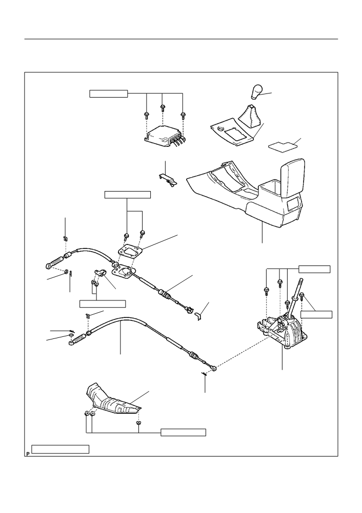
COMPONENTS
Floor Shift Lever
17.5 (178, 13)
Knob Sub-assy
Console Panel Upper
Console Box Carpet
Parking Brake Hole Cover Sub-assy
5.0 (51, 44 in. lbf)
Clip
Shift Cable Grommet
Retainer No. 1
Console Box Sub-assy Rear
Floor Shift Cable Transmission
Control Shift
12 (122, 9)
Washer
Clamp
Clip
Clip
5.0 (51, 44 in. lbf)
Clip
12 (122, 9)
Clip
Washer
Floor Shift Cable Transmission
Control Select
Floor Shift Shift Lever Assy
Front Floor Heat Insulator
Clip
5.5 (56, 49 in. lbf)
Nm (kgfcm, ftlbf)
: Specified torque
B53749

41-6
MANUAL TRANSMISSION/TRANSAXLE
- FLOOR SHIFT SHIFT LEVER ASSY
4107B-01
REPLACEMENT
HINT:
COMPONENTS: See page 41-5
1.
REMOVE FLOOR SHIFT SHIFT LEVER KNOB SUB-ASSY
2.
REMOVE CONSOLE PANEL UPPER (See page 71-10)
3.
REMOVE PARKING BRAKE HOLE COVER SUB-ASSY (See page
71-10)
4.
REMOVE CONSOLE BOX SUB-ASSY REAR (See page 71-10)
5.
SEPARATE FLOOR SHIFT CABLE TRANSMISSION
CONTROL SHIFT
(a) Separate the end of the shift cable from the shift lever
assy.
D26974
(b) Using a screwdriver, release the cable outer spring.
Cable Outer
(c)
Turn the lock, separate the shift cable from the shift lever
Spring
retainer.
Lock
D26973
6.
SEPARATE FLOOR SHIFT CABLE TRANSMISSION
CONTROL SELECT
(a) Separate the end of the select cable from the shift lever
assy.
D26976
(b) Using a screwdriver, release the cable outer spring.
(c)
Turn the lock, separate the select cable from the shift le-
ver retainer.
Cable Outer
spring
Lock
D26975
41-7
MANUAL TRANSMISSION/TRANSAXLE
- FLOOR SHIFT SHIFT LEVER ASSY
7.
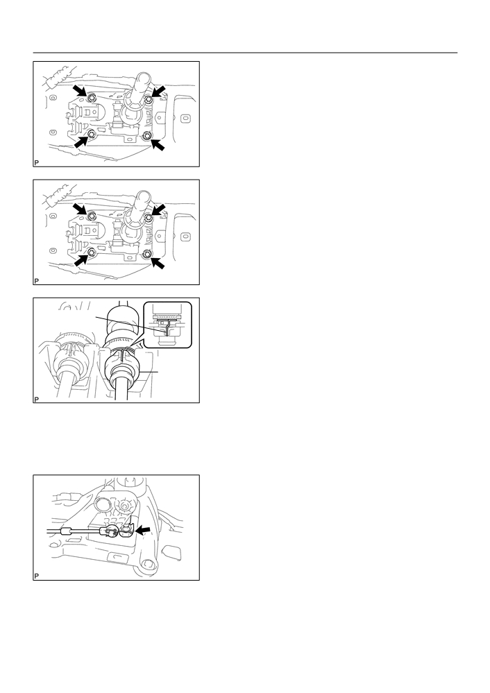
REMOVE FLOOR SHIFT SHIFT LEVER ASSY
(a) Remove the 4 bolts and shift lever assy.
D26889
8.
INSTALL FLOOR SHIFT SHIFT LEVER ASSY
(a) Install the shift lever assy with the 4 bolts.
Torque: 12 N m (120 kgf cm, 9 ft lbf)
D26889
9.
CONNECT FLOOR SHIFT CABLE TRANSMISSION
Cable Outer
CONTROL SHIFT
spring
(a) Connect the shift cable to the retainer of shift lever assy,
turn the lock.
NOTICE:
The projecting part of the lock should face upward when
Lock
the shift cable is installed.
(b) Install the cable outer spring to the lock.
D26915
NOTICE:
Make sure that after installation the cable outer spring is
moved to the place shown in the illustration.
(c)
Connect the end of the shift cable to the shift lever assy.
D26974

41-8
MANUAL TRANSMISSION/TRANSAXLE
- FLOOR SHIFT SHIFT LEVER ASSY
10. CONNECT FLOOR SHIFT CABLE TRANSMISSION
Cable Outer
CONTROL SELECT
spring
(a) Connect the select cable to the retainer of shift lever assy,
turn the lock.
NOTICE:
The projecting part of the lock should face upward when
the select cable is installed.
Lock
(b) Install the cable outer spring to the lock.
D26916
NOTICE:
Make sure that after installation the cable outer spring is
moved to the place shown in the illustration.
(c)
Connect the end of the select cable to the shift lever assy.
D26976
41-3
MANUAL TRANSMISSION/TRANSAXLE
- FRONT DIFFERENTIAL OIL SEAL
FRONT DIFFERENTIAL OIL SEAL
41077-02
REPLACEMENT
1.
DRAIN MANUAL TRANSAXLE OIL
Torque: 39.2 N m (400 kgf cm, 29 ft lbf)
2.
REMOVE FRONT WHEELS
3.
REMOVE ENGINE UNDER COVER LH
4.
REMOVE ENGINE UNDER COVER RH
5.
DRAIN TRANSAXLE OIL
6.
REMOVE FRONT DRIVE SHAFT ASSY LH (See page 30-6)
SST
09520-01010, 09520-24010 (09520-32040)
7.
REMOVE FRONT DRIVE SHAFT ASSY RH (See page 30-6)
SST
09520-01010, 09520-24010 (09520-32040)
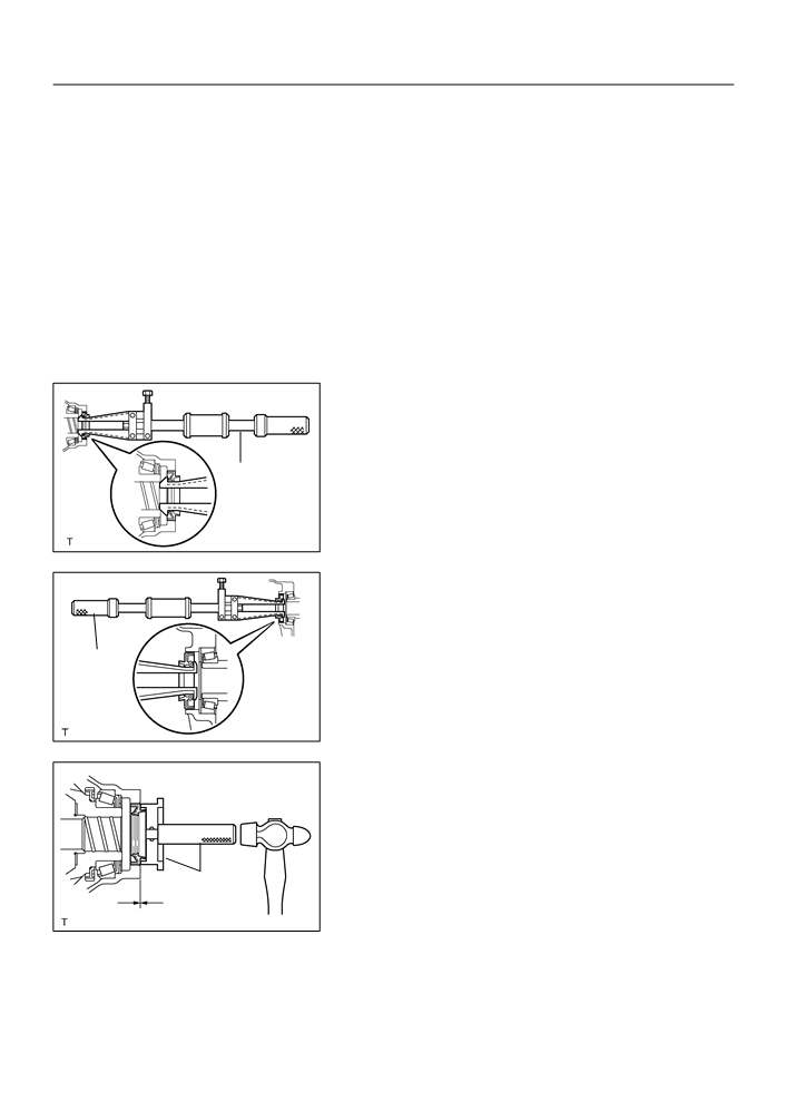
8.
REMOVE TRANSAXLE CASE OIL SEAL
(a) Using SST, remove the transaxle case oil seal.
SST
09308-00010
SST
C94266
9.
REMOVE TRANSMISSION CASE OIL SEAL
(a) Using SST, remove the transmission case oil seal.
SST
09308-00010
SST
D25305
10. INSTALL TRANSAXLE CASE OIL SEAL
(a) Coat a new oil seal lip with MP grease.
(b) Using SST and a hammer, install the transaxle case oil
seal.
SST
09554-14010, 09950-70010 (09951-07200)
Drive in depth: 1.9
0.3 mm (0.075
0.012 in.)
SST
NOTICE:
Be careful not to damage the oil seal lip.
D25722