Toyota Corolla (2004+). Manual - part 23
40-12
AUTOMATIC TRANSMISSION / TRANS
- AUTOMATIC TRANSAXLE ASSY (ATM)
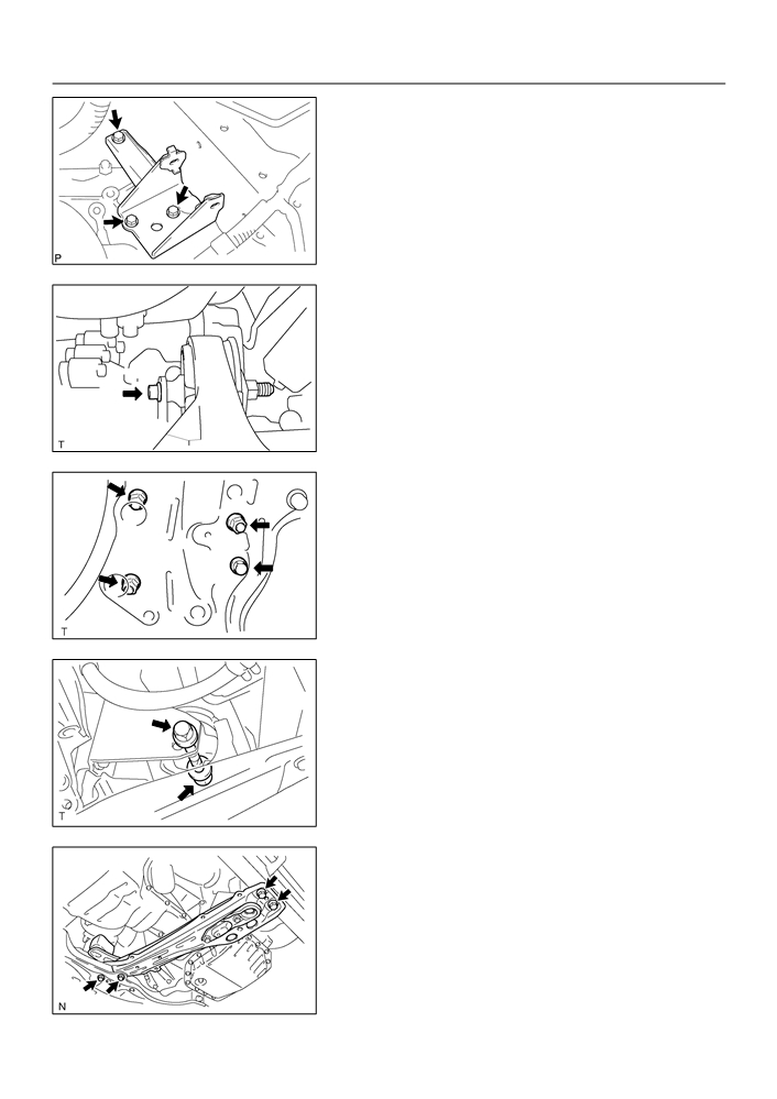
27. REMOVE TRANSVERSE ENGINE ENGINE
MOUNTING BRACKET
(a) Remove the 3 bolts and engine mounting bracket LH.
D09965
28. REMOVE TRANSVERSE ENGINE ENGINE
MOUNTING INSULATOR
(a) Remove the bolt from the engine mounting bracket RR.
C80192
(b) Remove the 3 nuts, bolt and engine mounting insulator
RR from the suspension member.
C80167
29. REMOVE TRANSVERSE ENGINE ENGINE
MOUNTING INSULATOR
(a) Remove the bolt and nut from the engine mounting brack-
et FR.
C80166
30. REMOVE ENGINE MOUNTING MEMBER SUB-ASSY
CENTER
(a) Remove the 4 bolts, dynamic damper and member sub-
assy center with engine mounting insulator FR.
C95354

40-13
AUTOMATIC TRANSMISSION / TRANS
- AUTOMATIC TRANSAXLE ASSY (ATM)
31. REMOVE TRANSVERSE ENGINE ENGINE
MOUNTING BRACKET
(a) Remove the 2 bolts and engine mounting bracket FR.
C80172
32. REMOVE TRANSVERSE ENGINE ENGINE
MOUNTING BRACKET
(a) Remove the 3 bolts and engine mounting bracket RR.
C93645
33. REMOVE FLYWHEEL HOUSING UNDER COVER
34. REMOVE AUTOMATIC TRANSAXLE ASSY
(a) Turn the crankshaft to gain access and remove the 6 bolts
while holding the crankshaft pulley bolt with a wrench.
F00478
(b) Remove the 6 bolts.
(c)
Separate and remove the automatic transaxle.
D09966
35. REMOVE TORQUE CONVERTER CLUTCH ASSY
36. INSPECT TORQUE CONVERTER CLUTCH ASSY (See page 40-20)
SST
09350-32014 (09351-32010, 09351-32020)

40-14
AUTOMATIC TRANSMISSION / TRANS
- AUTOMATIC TRANSAXLE ASSY (ATM)
37. INSTALL TORQUE CONVERTER CLUTCH ASSY
(a) Install the torque converter clutch to the automatic trans-
axle.
(b) Using vernier calipers, measure the dimension ”A” be-
tween the transaxle fitting part and the converter fitting
part of the drive plate.
C63993
(c)
Using vernier calipers and a straight edge, measure the
dimension ”B” shown in the illustration and check that ”B”
is greater than ”A” measured in (b).
Standard: A + 1 mm or more
NOTICE:
Do not add the thickness of straight edge.
C65911
38. INSTALL AUTOMATIC TRANSAXLE ASSY
(a) Install the automatic transaxle and 6 bolts to the engine.
Torque:
A
Bolt A: 64 N m (650 kgf cm, 47 ft lbf)
B
Bolt B: 46 N m (470 kgf cm, 34 ft lbf)
C
Bolt C: 23 N m (235 kgf cm, 17 ft lbf)
D09966
(b) Install the 6 torque converter mounting bolts.
Torque: 28 N m (285 kgf cm, 20 ft lbf)
HINT:
First install yellowish green colored bolt and then the 5 bolts.
F00478
39. INSTALL FLYWHEEL HOUSING UNDER COVER

40-15
AUTOMATIC TRANSMISSION / TRANS
- AUTOMATIC TRANSAXLE ASSY (ATM)
40. INSTALL TRANSVERSE ENGINE ENGINE MOUNTING
BRACKET
(a) Install the engine mounting bracket RR and 3 bolts to the
automatic transaxle.
Torque: 64 N m (652 kgf cm, 47 ft lbf)
C93645
41. INSTALL TRANSVERSE ENGINE ENGINE MOUNTING
BRACKET
(a) Install the engine mounting bracket FR and 2 bolts to the
automatic transaxle.
Torque: 64 N m (652 kgf cm, 47 ft lbf)
C80172
42. INSTALL ENGINE MOUNTING MEMBER SUB-ASSY
A
CENTER
A
(a) Install the dynamic damper, member sub-assy center
with engine mounting insulator FR and 4 bolts.
Torque:
Bolt A: 39 N m (398 kgf cm, 29 ft lbf)
Bolt B: 52 N m (530 kgf cm, 38 ft lbf)
B
B
C95354
43. INSTALL TRANSVERSE ENGINE ENGINE MOUNTING
INSULATOR
(a) Install the engine mounting insulator RR and bolt to the
engine mounting bracket RR.
Torque: 87 N m (887 kgf cm, 64 ft lbf)
C80192
(b) Tighten the 3 nuts and bolt.
Torque: 52 N m (530 kgf cm, 38 ft lbf)
C80167

40-16
AUTOMATIC TRANSMISSION / TRANS
- AUTOMATIC TRANSAXLE ASSY (ATM)
44. INSTALL TRANSVERSE ENGINE ENGINE MOUNTING
BRACKET
(a) Install the engine mounting bracket LH and 3 bolts to the
automatic transaxle.
Torque: 52 N m (530 kgf cm, 38 ft lbf)
D09965
45. INSTALL TRANSVERSE ENGINE ENGINE MOUNTING
A
A
INSULATOR
(a) Install the engine mounting insulator LH, 5 bolts and nut.
A
B
Torque:
Bolt A: 52 N m (530 kgf cm, 38 ft lbf)
Bolt B: 80 N m (815 kgf cm, 59 ft lbf)
Nut B: 80 N m (815 kgf cm, 59 ft lbf)
B
A
D09964
46. INSTALL TRANSVERSE ENGINE ENGINE MOUNTING
INSULATOR
(a) Install the bolt and nut to the engine mounting bracket FR.
Torque: 52 N m (530 kgf cm, 38 ft lbf)
C80166
47. INSTALL STARTER ASSY
(a) Install the starter and 2 bolts.
Torque: 39 N m (400 kgf cm, 29 ft lbf)
(b) Connect the connecter.
(c)
Install the starter wire and nut.
Torque: 13 N m (132 kgf cm, 10 ft lbf)
48. INSTALL AUTOMATIC TRANSMISSION CASE PROTECTOR
(a) Install the case protector with the 2 bolts.
Torque: 18 N m (182 kgf cm, 14 ft lbf)
49. INSTALL FRONT DRIVE SHAFT ASSY LH (See page 30-6)
50. INSTALL FRONT DRIVE SHAFT ASSY RH (See page 30-6)
51. INSTALL EXHAUST PIPE ASSY FRONT (See page 15-2)
52. INSTALL ENGINE UNDER COVER LH
53. INSTALL ENGINE UNDER COVER RH
54. INSTALL FRONT WHEELS
Torque: 103 N m (1,050 kgf cm, 76 ft lbf)
55. INSTALL OXYGEN SENSOR CONNECTOR
(a) Connect the oxygen sensor connector.
(b) Install the floor carpet and foot rest.
40-17
AUTOMATIC TRANSMISSION / TRANS
- AUTOMATIC TRANSAXLE ASSY (ATM)
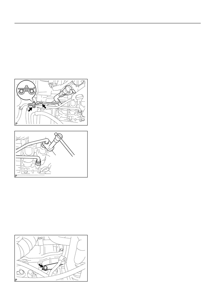
56. INSTALL TRANSMISSION OIL FILLER TUBE
SUB-ASSY
(a) Temporarily install the oil cooler outlet tube No. 1.
(b) Temporarily install the oil cooler inlet tube No. 1.
(c)
Coat a new O-ring with ATF, and install them to the oil filler
tube.
(d) Install the oil filler tube to the automatic transaxle.
(e) Install the oil cooler tube clamp and 2 bolts.
Torque: 5.5 N m (56 kgf cm, 49 in. lbf)
(f)
Install the ATF lever gauge.
D09962
57. INSTALL OIL COOLER INLET TUBE NO.1
(a) Using SST, tighten the oil cooler inlet tube No. 1.
SST
09023-12700
Torque: 34.5 N m (350 kgf cm, 25 ft lbf)
SST
C93646
58. INSTALL OIL COOLER OUTLET TUBE NO.1
(a) Using SST, tighten the oil cooler outlet tube No. 1.
SST
09023-12700
Torque: 34.5 N m (350 kgf cm, 25 ft lbf)
59. CONNECT CONNECTOR
(a) Connect the transmission wire connector.
(b) Connect the park/neutral position switch connector.
(c)
w/o ABS:
Connect the speedometer sensor connector.
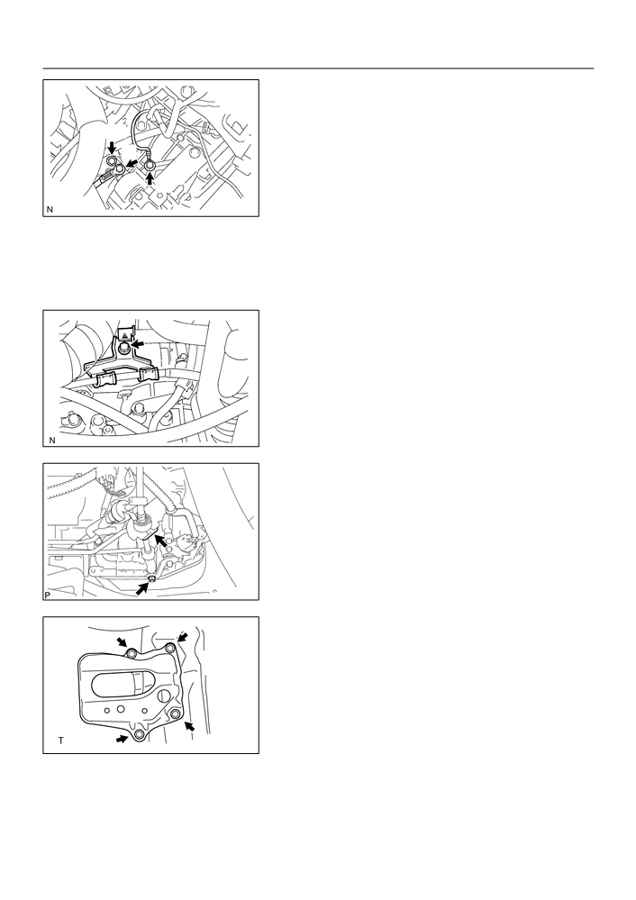
60. INSTALL WIRE HARNESS
(a) Install the wire harness clamp bracket and bolt.
Torque: 12.75 N m (130 kgf cm, 9 ft lbf)
C93643
40-18
AUTOMATIC TRANSMISSION / TRANS
- AUTOMATIC TRANSAXLE ASSY (ATM)
(b) Install the wire harness clamp bracket and 2 wire har-
nesses with the 3 bolts.
Torque:
A
Bolt A: 25.5 N m (260 kgf cm, 19 ft lbf)
Bolt B: 10 N m (102 kgf cm, 7 ft lbf)
C
Bolt C: 13 N m (132 kgf cm, 10 ft lbf)
B
C93666
61. INSTALL TRANSMISSION CONTROL CABLE BRACKET NO.1
(a) Install the control cable bracket and 2 bolts.
Torque: 12 N m (122 kgf cm, 9 ft lbf)
62. INSTALL TRANSMISSION CONTROL CABLE
SUPPORT
(a) Install the control cable support and bolt.
Torque: 12 N m (122 kgf cm, 9 ft lbf)
(b) Connect the control cable and wire harness to the control
cable support.
C95750
63. INSTALL FLOOR SHIFT CABLE TRANSMISSION
CONTROL SHIFT
(a) Temporarily install the control cable to the control shaft le-
ver with the nut.
(b) Install the control cable and clip to the bracket.
C96147
64. INSTALL BATTERY CARRIER
(a) Install the battery carrier and 4 bolts.
Torque: 13 N m (132 kgf cm, 10 ft lbf)
C80159
65. INSTALL AIR CLEANER ASSEMBLY WITH HOSE
Torque: 7.0 N m (71 kgf cm, 62 in. lbf)
66. INSTALL CYLINDER HEAD COVER NO.2
Torque: 7.0 N m (71 kgf cm, 62 in. lbf)
40-19
-
AUTOMATIC TRANSMISSION / TRANS
AUTOMATIC TRANSAXLE ASSY (ATM)
67. INSTALL HOOD SUB-ASSY
Torque: 13 N m (130 kgf cm, 10 ft lbf)
68. INSPECT HOOD SUB-ASSY (See page 75-1)
69. ADJUST HOOD SUB-ASSY (See page 75-1)
70. ADD AUTOMATIC TRANSAXLE FLUID
71. INSPECT AUTOMATIC TRANSAXLE FLUID (See page 40-2)
72. ADJUST SHIFT LEVER POSITION (See page 40-44)
73. INSPECT SHIFT LEVER POSITION (See page 40-44)
74. INSPECT FRONT WHEEL ARIMENT (See page 26-5)
75. CHECK ABS SPEED SENSOR SIGNAL (W/ ABS) (See page
05-297)

40-44
AUTOMATIC TRANSMISSION / TRANS
- FLOOR SHIFT ASSY (ATM)
400LS-01
ADJUSTMENT
1.
INSPECT SHIFT LEVER POSITION
(a)
When shifting the shift lever to each position, make sure
that it moves smoothly, and the position indicator displays
correctly.
Positions which can be shifted without pressing the
shift lever knob button
R N D, L 2 D N
Positions which can be operated only while pressing
the shift lever knob button
D 2 L, N R P
Positions which can be operated only while pressing
With the brake pedal depressed,
the shift lever knob button, ignition switch ON and
shift while holding the shift lever
brake pedal depressed
knob button in. (The ignition
P R
switch must be in ON position.)
(b)
Start the engine and make sure that the vehicle moves
Shift while holding the shift
forward when shifting the lever from N to D position, and
lever knob button in.
moves rearward when shifting to R position.
Shift normally
C95423
2.
ADJUST SHIFT LEVER POSITION
(a)
Loosen the nut on the control shaft lever.
D25118
(b) Push the control shaft fully downward.
(c)
Return the control shaft lever 2 notches to N position.
(d) Set the shift lever to N position.
(e) While holding the shift lever lightly toward the R position
side, tighten the shift lever nut.
Torque: 12 N·m (122 kgf·cm, 9 ft·lbf)
(f)
Start the engine and make sure that the vehicle moves
forward when shifting the lever from N to D position and
D25119
moves rearward when shifting it to R position.

40-32
AUTOMATIC TRANSMISSION / TRANS
- FLOOR SHIFT ASSY (ATM)
FLOOR SHIFT ASSY (ATM)
400LQ-01
COMPONENTS
Console Panel Upper
Console Box Carpet
Parking Brake Hole Cover Sub-assy
Console Box Sub-assy Rear
Floor Shift Parking Lock Cable Assy
12 (122, 9)
12 (122, 9)
Floor Shift Cable Transmission
Control Shift
Floor Shift Assy
Nm (kgfcm, ftlbf)
: Specified torque
C95783

40-33
AUTOMATIC TRANSMISSION / TRANS
- FLOOR SHIFT ASSY (ATM)
Shift Lock Release Button
Position Indicator Housing Lower
Spring
Shift Lever Knob Sub-assy
Transmission Control Switch
Spring
Shift Lever
Cap
F
Knob Cover
Bulb
Indicator Lamp Wire Sub-assy
Shift Lever Knob Button
Shift Lock Release Button Cover
Position Indicator Housing Upper
Shift Lock Control
Toggle Lever
Unit Assy
Support Pin
Position Indicator
Control Position
Slide Cover
Indicator Plate
Shift Lever Insert No.1
Shift Lever Plate Sub-assy
C93668
Shift Lever
Insert No.1
F Precoated part
Apply MP grease
C93668

40-34
AUTOMATIC TRANSMISSION / TRANS
- FLOOR SHIFT ASSY (ATM)
400LR-01
OVERHAUL
1.
REMOVE CONSOLE PANEL UPPER (See page 71-10)
2.
REMOVE CONSOLE BOX CARPET (See page 71-10)
3.
REMOVE PARKING BRAKE HOLE COVER SUB-ASSY (See page
71-10)
4.
REMOVE CONSOLE BOX SUB-ASSY REAR (See page 71-10)
5.
DISCONNECT FLOOR SHIFT CABLE TRANSMISSION
CONTROL SHIFT
(a) Remove the cable end from the rod of the floor shift as-
sembly.
C93669
(b) Using a screw driver, disconnect the control cable from
the shift lever plate.
C94276
6.
DISCONNECT FLOOR SHIFT PARKING LOCK CABLE
ASSY
(a) Remove the cable end from the lever pin of the floor shift
assembly.
C93670
(b) Using a screw driver, disconnect the parking lock cable
from the floor shift assembly.
7.
REMOVE FLOOR SHIFT ASSY
(a) Disconnect the 2 connector.
C94278

40-35
AUTOMATIC TRANSMISSION / TRANS
- FLOOR SHIFT ASSY (ATM)
(b) Disconnect the 2 wire harness clamps from the shift lever
assy.
(c)
Remove the 4 bolts and floor shift assy.
C93671
8.
REMOVE FLOOR SHIFT SHIFT LEVER KNOB
SUB-ASSY
(a) Releasing the lock by pressing the slick, disconnect the
indicator lamp wire connector from the shift lever plate.
C93672
(b) Disengage the secondary locking device.
1
Secondary Locking Device
(c)
Using a small screwdriver, disengage the locking lug of
the terminals 2 and 4, and pull the terminals out from the
rear.
(d) Disconnect the wire harness from the clamps.
4
2
3
2
C95784
(e) Remove the 2 screws and shift lever knob sub-assembly.
NOTICE:
Pay attention not to apply unnatural load to transmission
control switch wire harness.
C93673
9.
REMOVE FLOOR SHIFT SHIFT LEVER KNOB COVER
(a) Remove the shift lever knob cover.
C93674

40-36
AUTOMATIC TRANSMISSION / TRANS
- FLOOR SHIFT ASSY (ATM)
10. REMOVE TRANSMISSION CONTROL SWITCH
(a) Using a small screw driver, remove the transmission con-
trol switch.
C93675
11. REMOVE SHIFT LEVER KNOB BUTTON
(a) Remove the shift lever knob button and spring.
C93676
12. REMOVE INDICATOR LAMP WIRE SUB-ASSY
(a) Remove the indicator lamp wire sub-assy.
(b) Remove the cap and bulb from the indicator lamp wire
sub-assy.
C93677
13. REMOVE SHIFT LOCK RELEASE BUTTON COVER
(a) Using a screwdriver, remove the shift lock release button
cover.
C93678
14. REMOVE POSITION INDICATOR HOUSING UPPER
(a) Using a screwdriver, release the 4 claws and remove the
position indicator housing upper.
C93679

40-37
AUTOMATIC TRANSMISSION / TRANS
- FLOOR SHIFT ASSY (ATM)
15. REMOVE CONTROL POSITION INDICATOR PLATE
(a) Remove the position indicator plate from the position indi-
cator housing upper.
C93680
16. REMOVE POSITION INDICATOR SLIDE COVER
(a) Remove the position indicator slide cover.
C95340
17. REMOVE POSITION INDICATOR HOUSING LOWER
(a) Using a screwdriver, release the 3 claws and remove the
position indicator housing lower.
C95341
18. REMOVE SHIFT LOCK RELEASE BUTTON
(a) Remove the shift lock release button and spring.
C95342
19. REMOVE SHIFT LOCK CONTROL UNIT ASSY
(a) Using a screwdriver, remove the toggle lever support pin
and shift lock control unit assy.
NOTICE:
Work so as not to damage the stopper position.
Stopper
C95343