Toyota Corolla (2004+). Manual - part 22
33-11
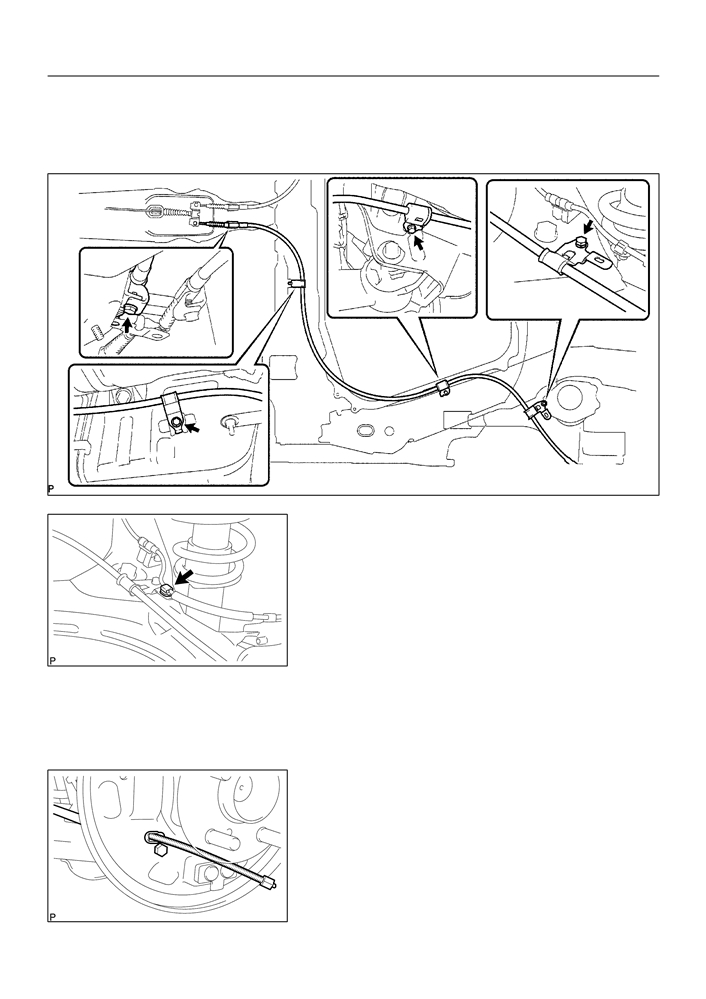
PARKING BRAKE
- PARKING BRAKE CABLE ASSY NO.3
(b) Install the parking brake cable assy No.3 with the 4 bolts
and cable retainer.
Torque: 5.4 N m (55 kgf cm, 48 in. lbf)
F42654
(c)
Connect the skid control sensor wire harness clip to the
clamp.
14. INSTALL FUEL TANK PROTECTOR NO.1
(a) Install the fuel tank protector No.1 with the 5 nuts.
Torque: 5.5 N m (55 kgf cm, 48 in. lbf)
F42653
15. INSTALL FRONT FLOOR HEAT INSULATOR NO.2 (See page
33-7)
16. INSTALL FRONT FLOOR HEAT INSULATOR NO.1 (See page
33-7)
17. INSTALL EXHAUST PIPE ASSY FRONT (See page 15-2)
18. CONNECT PARKING BRAKE CABLE ASSY NO.3
(a) Connect the parking brake cable assy No.3 to the backing
plate with the bolt.
Torque: 7.8 N m (80 kgf cm, 69 in. lbf)
F42652
33-12
PARKING BRAKE
- PARKING BRAKE CABLE ASSY NO.3
19. APPLICATION HIGH TEMPERATURE GREASE (See page 32-31)
20. INSTALL REAR BRAKE SHOE (See page
32-31)
SST
09718-00010
21. INSTALL PARKING BRAKE SHOE STRUT SET LH (See page
32-31)
22. INSTALL FRONT BRAKE SHOE (See page 32-31)
SST
09718-00010
23. INSTALL REAR BRAKE AUTOMATIC ADJUST LEVER LH (See page
32-31)
24. CHECK REAR DRUM BRAKE INSTALLATION (See page
32-31)
25. INSTALL REAR BRAKE DRUM SUB-ASSY
26. ADJUST REAR DRUM BRAKE SHOE CLEARANCE (See page
32-31)
27. INSTALL REAR WHEEL
Torque: 103 N m (1,050 kgf cm, 76 ft lbf)
28. INSPECT PARKING BRAKE LEVER TRAVEL (See page
33-2)
29. ADJUST PARKING BRAKE LEVER TRAVEL (See page
33-2)
30. CHECK EXHAUST LEAKAGE

33-3
PARKING BRAKE
- PARKING BRAKE LEVER SUB-ASSY
PARKING BRAKE LEVER SUB-ASSY
3307D-01
COMPONENTS
A/T:
Console Box
Carpet
M/T:
Floor Shift Shift
Lever Knob Sub-assy
Console Panel Upper
Console Panel Upper
Parking Brake
Hole Cover Sub-assy
A/T:
Console Box
Sub-assy Rear
Connector
Lock Nut
Parking Brake
5.0 (55, 44 in. lbf)
Lever Sub-assy
Adjusting Nut
12.5 (130, 9)
Screw
12.5 (130, 9)
Parking Brake
Switch Assy
Parking Brake
Switch Connector
Parking Brake
Cable No.1
Nm (kgfcm, ftlbf)
: Specified torque
F42667

33-4
PARKING BRAKE
- PARKING BRAKE LEVER SUB-ASSY
3307E-01
REPLACEMENT
1.
REMOVE CONSOLE BOX SUB-ASSY REAR (See page 71-10)
2.
REMOVE PARKING BRAKE LEVER SUB-ASSY
(a) Disconnect the parking brake switch connector from the
parking brake switch.
(b) Remove the lock nut and adjusting nut from the parking
brake cable assy No.1.
F41837
(c)
Remove the 2 bolts.
F41838
(d) Using a screwdriver, raise the pick on the parking brake
lever, and remove the parking brake cable assy No.1 from
the parking brake lever.
(e) Remove the parking brake lever from the body.
F42264
3.
REMOVE PARKING BRAKE SWITCH ASSY
(a) Remove the screw and parking brake switch assy.
F41840

33-5
PARKING BRAKE
- PARKING BRAKE LEVER SUB-ASSY
4.
INSTALL PARKING BRAKE SWITCH ASSY
(a) Install the parking brake switch to the parking brake lever
sub-assy with the screw.
F41840
5.
INSTALL PARKING BRAKE LEVER SUB-ASSY
(a) Install the parking brake cable assy No.1 to the parking
brake lever, temporarily tighten the adjusting nut and lock
nut.
(b) Using a screwdriver, fix the parking brake cable No.1 to
the pick.
F41841
(c)
Install the parking brake lever with the 2 bolts.
Torque: 12.5 N m (130 kgf cm, 9 ft lbf)
F41838
(d) Connect the parking brake switch connector to the park-
ing brake switch.
F41837
6.
INSPECT PARKING BRAKE LEVER TRAVEL (See page
33-2)
7.
ADJUST PARKING BRAKE LEVER TRAVEL (See page
33-2)
8.
INSTALL CONSOLE BOX SUB-ASSY REAR

33-1
PARKING BRAKE
- PARKING BRAKE SYSTEM
PARKING BRAKE SYSTEM
3307B-01
PROBLEM SYMPTOMS TABLE
Use the table below to help you find the cause of the problem. The numbers indicate the probability of the
problems in descending order. Check each part in order. If necessary, replace these parts.
Symptom
Suspect Area
See page
1. Parking brake lever travel (Out of adjustment)
33-2
2. Parking brake wire (Sticking)
33-7
33-10
Brake drag
3. Parking brake shoe clearance (Out of adjustment)
32-31
4. Parking brake shoe lining (Cracked or distorted)
32-31
5. Tension or return spring (Damaged)
32-31

40-6
AUTOMATIC TRANSMISSION / TRANS
- PARK/NEUTRAL POSITION SWITCH ASSY (ATM)
400LI-01
ADJUSTMENT
1.
INSPECT PARK/NEUTRAL POSITION SWITCH ASSY
(a) Apply the parking brake and turn the ignition switch ON.
(b) Depress the brake pedal and check that the engine starts only when the shift lever is set in N or P posi-
tion and it does not start in the other position.
(c)
Check that the back-up light comes on and the reverse warning buzzer sounds only when the shift
lever is set in R position and these do not function in the other positions.
If a failure is found, check the park/ neutral position switch for continuity.
2.
ADJUST PARK/NEUTRAL POSITION SWITCH ASSY
(a) Loosen the 2 bolts of park/ neutral position switch and set
Neutral
the shift lever to the N position.
Basic Line
(b) Align the groove and neutral basic line.
(c)
Hold the switch in position and tighten the 2 bolts.
Torque: 5.5 N m (56 kgf cm, 49 in. lbf)
(d) After adjustment, perform the inspection described in
Groove
step 1.
D25514

40-3
AUTOMATIC TRANSMISSION / TRANS
- PARK/NEUTRAL POSITION SWITCH ASSY (ATM)
PARK/NEUTRAL POSITION SWITCH ASSY (ATM)
400LH-01
REPLACEMENT
1.
REMOVE BATTERY
2.
REMOVE BATTERY CARRIER
(a) Remove the 4 bolts and battery carrier.
C80159
3.
DISCONNECT FLOOR SHIFT CABLE TRANSMISSION
CONTROL SHIFT
(a) Remove the nut from the control shaft lever.
(b) Disconnect the control cable from the control shaft lever.
(c)
Remove the clip and disconnect the control cable from
the control cable bracket.
C96147
4.
REMOVE PARK/NEUTRAL POSITION SWITCH ASSY
(a) Disconnect the park/neutral position switch connector.
(b) Remove the nut, washer and control shaft lever.
(c)
Pry out the lock plate and remove the manual valve shaft
nut.
(d) Remove the 2 bolts and pull out the park/neutral position
switch.
D25124
5.
INSTALL PARK/NEUTRAL POSITION SWITCH ASSY
(a) Install the park/neutral position switch to the manual valve
shaft.
(b) Temporarily install the 2 bolts.
(c)
Place a new lock plate and tighten the nut.
Torque: 5.5 N m (56 kgf cm, 49 in. lbf)
(d) Temporarily install the control shaft lever.
D09957

40-4
AUTOMATIC TRANSMISSION / TRANS
- PARK/NEUTRAL POSITION SWITCH ASSY (ATM)
(e) Turn the lever counterclockwise until it stops, then turn it
clockwise 2 notches.
(f)
Remove the control shaft lever.
D25126
(g) Align the groove with neutral basic line.
Neutral
(h) Hold the switch in position and tighten the 2 bolts.
Basic Line
Torque: 5.5 N m (56 kgf cm, 49 in. lbf)
Groove
D08584
(i)
Using a screwdriver, stake the nut with the lock plate.
D08585
(j)
Install the control shaft lever, washer and nut.
Torque: 12.5 N m (127 kgf cm, 9 ft lbf)
(k)
Connect the park/neutral position switch connector.
D25125
6.
INSTALL FLOOR SHIFT CABLE TRANSMISSION
CONTROL SHIFT
(a) Temporarily install the control cable to the control shaft le-
ver with nut.
(b) Install the control cable and clip to the bracket.
C96147

40-5
AUTOMATIC TRANSMISSION / TRANS
- PARK/NEUTRAL POSITION SWITCH ASSY (ATM)
7.
INSTALL BATTERY CARRIER
(a) Install the battery carrier and 4 bolts.
Torque: 13 N m (132 kgf cm, 10 ft lbf)
C80159
8.
ADJUST SHIFT LEVER POSITION (See page 40-44)
9.
INSPECT SHIFT LEVER POSITION (See page 40-44)
10. INSPECT PARK/NEUTRAL POSITION SWITCH ASSY (See page 40-6)

40-7
AUTOMATIC TRANSMISSION / TRANS
- AUTOMATIC TRANSAXLE ASSY (ATM)
AUTOMATIC TRANSAXLE ASSY (ATM)
400LJ-01
COMPONENTS
Hood Sub-assy
Air Cleaner Assy
13 (132, 10)
7.0 (71, 62 in. lbf)
7.0 (71, 62 in. lbf)
Battery
Cylinder Head
12 (122, 9)
Cover No.2
12.75 (130, 9)
13 (132, 10)
10 (102, 7)
Control Cable Support
25.5 (260, 19)
Starter Assy
39 (400, 29)
13 (132, 10)
w/o ABS:
Oil Cooler Inlet Tube No.1
Oil Cooler Outlet
Tube No.1
39 (400, 29)
13 (132, 10)
Floor Shift Cable Transmission
34.5 (350, 25)
Control Shift
5.5 (56, 49 in. lbf)
Clip
Speedometer sensor
connector
Transmission Oil Filler
Tube Sub-assy
Battery Carrier
5.5 (56, 49 in. lbf)
12 (122, 9)
Automatic Transaxle Assy
F O-ring
ATF Level Gauge
12 (122, 9)
Transmission Control Cable
Nm (kgfcm, ftlbf)
: Specified torque
Bracket No.1
F Non-reusable part
C95348

40-8
AUTOMATIC TRANSMISSION / TRANS
- AUTOMATIC TRANSAXLE ASSY (ATM)
80 (815, 59)
Front Drive Shaft Assy RH
52 (530, 38)
52 (530, 38)
F Snap Ring
Engine Mounting
Bracket LH
Torque Converter Clutch Assy
64 (650, 47)
Engine Mounting
52 (530, 38)
Insulator LH
x 6
46 (470, 34)
28 (285, 20)
F Snap Ring
23 (235, 17)
Front Drive Shaft Assy LH
Flywheel Housing Under Cover
Transmission Case Protector
18 (182, 14)
Automatic Transaxle Assy
Engine Mounting Insulator RR
Engine Mounting
87 (887, 64)
Bracket RR
64 (652, 47)
Engine Mounting Bracket FR
64 (652, 47)
Engine Under Cover RH
52 (530, 38)
52 (530, 38)
Engine Under Cover LH
64 (652, 47)
64 (652, 47)
52 (530, 38)
Front Suspension Member Dynamic
Damper
52 (530, 38)
Engine Mounting Member
Sub-assy Center
Nm (kgfcm, ftlbf)
: Specified torque
39 (398, 29)
F Non-reusable part
C95349

40-9
AUTOMATIC TRANSMISSION / TRANS
- AUTOMATIC TRANSAXLE ASSY (ATM)
400LK-02
REPLACEMENT
1.
REMOVE HOOD SUB-ASSY
2.
REMOVE CYLINDER HEAD COVER NO.2
3.
REMOVE BATTERY
4.
REMOVE BATTERY CARRIER
(a) Remove the 4 bolts and battery carrier.
C80159
5.
REMOVE AIR CLEANER ASSEMBLY WITH HOSE
6.
REMOVE FLOOR SHIFT CABLE TRANSMISSION
CONTROL SHIFT
(a) Remove the nut from the control shaft lever.
(b) Disconnect the control cable from the control shaft lever.
(c)
Remove the clip and disconnect the control cable from
the control cable bracket.
C96147
7.
REMOVE TRANSMISSION CONTROL CABLE
SUPPORT
(a) Disconnect the wire harness clamp and control cable
from the control cable support.
(b) Remove the bolt and control cable support.
C95750
8.
REMOVE TRANSMISSION CONTROL CABLE BRACKET NO.1
(a) Remove the 2 bolts and control cable bracket.

40-10
AUTOMATIC TRANSMISSION / TRANS
- AUTOMATIC TRANSAXLE ASSY (ATM)
9.
DISCONNECT WIRE HARNESS
(a) Remove the 2 bolts and disconnect the 2 wire harnesses.
(b) Remove the bolt and disconnect the wire harness clamp
bracket.
C93666
(c)
Remove the bolt and disconnect the wire harness clamp
bracket.
C93643
10. DISCONNECT CONNECTOR
(a) Disconnect the transmission wire connector.
(b) Disconnect the park/neutral position switch connector.
(c)
w/o ABS:
Disconnect the speedometer sensor connector.
11. REMOVE TRANSMISSION OIL FILLER TUBE
SUB-ASSY
(a) Remove the ATF lever gauge.
(b) Remove the 2 bolts, oil cooler tube clamp and oil filler
tube.
(c)
Remove the O-ring from the oil filler tube.
D09961
12. DISCONNECT OIL COOLER INLET TUBE NO.1
(a) Using SST, disconnect the oil cooler inlet tube No. 1.
SST
09023-12700
SST
C93646
13. DISCONNECT OIL COOLER OUTLET TUBE NO.1
(a) Using SST, disconnect the oil cooler outlet tube No. 1.
SST
09023-12700

40-11
AUTOMATIC TRANSMISSION / TRANS
- AUTOMATIC TRANSAXLE ASSY (ATM)
14. DISCONNECT OXYGEN SENSOR CONNECTOR
(a) Remove the foot rest.
(b) Pull up the floor carpet.
(c)
Disconnect the oxygen sensor connector.
No. 1
No. 2
15. SUSPEND ENGINE ASSY
Engine Hanger
Engine Hanger
(a) Disconnect the 2 PCV hoses.
(b) Install the No.1 and No.2 engine hangers in the correct
direction.
Parts No.:
No.1 engine hanger: 12281-22021
No.2 engine hanger: 12281-15040
Bolt: 91512-B1016
Front
Rear
Torque: 38 N m (387 kgf cm, 28 ft lbf)
D25372
(c)
Attach the engine chain hoist to the engine hangers.
CAUTION:
Do not attempt to hang the engine by hooking the chain to
any other parts.
16.
REMOVE FRONT WHEELS
17.
REMOVE ENGINE UNDER COVER RH
18.
REMOVE ENGINE UNDER COVER LH
19.
DRAIN AUTOMATIC TRANSAXLE FLUID
(a)
Remove the drain plug and gasket, and drain ATF.
(b)
Install a new gasket and drain plug.
Torque: 17.5 N m (178 kgf cm, 13 ft lbf)
20.
REMOVE EXHAUST PIPE ASSY FRONT (See page 15-2)
21.
REMOVE FRONT DRIVE SHAFT ASSY RH (See page 30-6)
SST
09520-01010, 09520-24010 (09520-32040)
22.
REMOVE FRONT DRIVE SHAFT ASSY LH (See page 30-6)
SST
09520-01010, 09520-24010 (09520-32040)
23.
REMOVE AUTOMATIC TRANSMISSION CASE PROTECTOR
(a)
Remove the 2 bolts and case protector.
24.
REMOVE STARTER ASSY
(a)
Remove the nut and disconnect the starter wire.
(b)
Disconnect the connector.
(c)
Remove the 2 bolts and starter.
25.
SUPPORT AUTOMATIC TRANSAXLE ASSY
(a)
Support the automatic transaxle with a transmission jack.
26. REMOVE TRANSVERSE ENGINE ENGINE
MOUNTING INSULATOR
(a) Remove the 5 bolts, nut and engine mounting insulator
LH.
D09964