SsangYong Rexton. Service manual - part 446


  Index      SsangYong     SsangYong Rexton - service and repair manual


Search            


Content   ..  444  445  446  447   ..


SsangYong Rexton. Service manual - part 446


SSANGYONG  Y200

1F3-4  DIESEL ENGINE CONTROLS

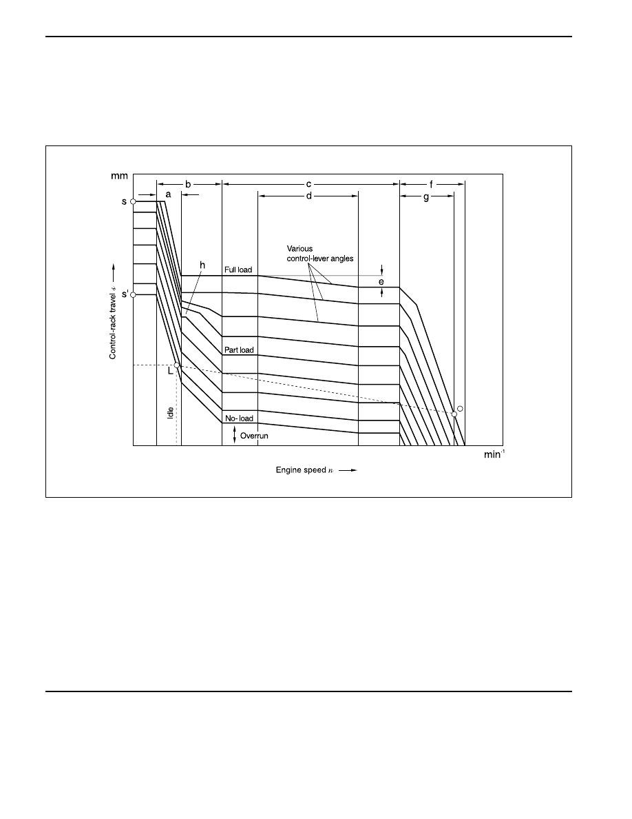
a Idle Range (Working Range of the Idle Spring)

b Extended Idle Range at No-Load and Minimum

Part Load (Working Range of the Idle Spring
and the Auxiliary Idle Spring)

c Uncontrolled Range

d Torque-Control Range (Working Range of the

Torque-Control Spring)

e Torque-Control Travel

f Speed-Regulation Range (Working Range of the

Governor Spring)

g Full-Load Speed Regulation to the High Idle

Speed

h Start of the Auxiliary Idle-Spring Shutoff

GOVERNOR

RSF Minimum-maximum-speed governor

The RSF mechanical governor was developed
specifically as a minimum-maximum-speed governor.
It is suitable for use in those on-road vehicles
(passenger cars and commercial vehicles) in which

YAD1FAC0

S Start Setting With Accelerator Pedal fully

Depressed (Cold-Start)

S ’ Start Setting With Accelerator Pedal Released

(Hot/ Warm Start)

L Low-Idle-Speed Setting

O High-Idle-Speed Setting

n

1u

Low Idle Speed

n

1o

High Idle Speed

n

vo

Maximum Full-Load Speed

n

1

Speed at Start of Torque Control

n

2

Speed at End of Torque Control

control requirements are restricted to low idle and high
idle (maximum) speeds.control requirements are
restricted to low idle and high idle (maximum) speeds.
In the uncontrolled range between these two speed,
the driver uses the accelerator pedal to directly adjust
the setting of the injection-pump control rack so that
the engine develops the right torque.

DIESEL ENGINE CONTROLS  1F3-5

SSANGYONG  Y200

Speed-sensing mechanism stage 1 (low idle)

The force path starts at flyweights (22) and travels
through sliding sleeve (20) and guide lever (9) to idle
spring (12) and auxiliary idle spring (14). Both springs
are leaf springs.

Speed-sensing machanism, stage 2
(until full-load speed regulation)

After completion of idle-speed sleeve travel, the force
path is from governor sliding sleeve (20) through
torque-control spring retainer (18) and tensioning lever
(16) to governor spring (17).

The flyweights (22) are fastened directly to the injection-
pump camshaft and when they move outward,
governor sliding sleeve (20) is moved axially. The
sliding sleeve does not move except in the idle, full-
load torque-control, and speed-regulation breakaway
ranges. The fuel delivery quantity needed for the
required engine torque is selected by the actuator-
mechanism control lever.

The guide lever (9) is movably connected at pivot point
B with the governor sliding sleeve. In addition, guide
lever and tensioning lever (16) also pivot at point A.

YAD1FAD0

1 Stop(Shutoff) Lever
2 Strap
3 Stop Lever
4 Control Rack
5 Linkage Lever (Inner)
6 Control Lever (Outer)
7 Full-Load Stop
8 Adjusting Screw For Idle Speed
9 Guide Lever

10 Idle Stop
11 Reverse-Transfer Lever
12 Idle-Speed Spring
13 Variable-Fulcrum Lever

14 Auxiliary Idle Spring
15 Adjusting Screw for Auxiliary Idle Spring

 16 Tensioning Lever

17 Governor Spring
18 Spring Retainer

(Torque Control)

19 Full-Load Adjusting Screw
20 Governor Sliding Sleeve
21 Auxiliary-Idle-Spring

Switch-Off Device

22 Flyweight

SSANGYONG  Y200

1F3-6  DIESEL ENGINE CONTROLS

Actuator mechanism

Input of the desired valve is through control lever (6)
linkage lever (5) and reverse-transfer lever (11) to
variable fulcrum lever (13), and from there through strap
(2) to injection-pump control rack (4). The strap is
spring-loaded, and compensates for the extra
movement of the fulcrum lever. Similar to the guide
lever, the reverse-transfer lever is also flexibly mounted
at pivot point B of the sliding sleeve, and is also
attached to the fulcrum lever (13) via a shaft and
bushing. Full-load delivery at the fulcrum lever’s lower
bearing point, which also acts as the spring-loaded
yield point for the fulcrum lever for absorbing the
sliding sleeve’s additional travel in case of excessive
speed. The bearing shaft of the stop lever (3) protrudes
from the governor housing. Attached to its end is a
stop (shutoff) lever (1) which switches off the engine,
whereby the stop lever pulls the control rack in the
stop (shoutoff) direction.

Starting the engine

The engine is to be started according to the vehicle
manufacturer’s operating instructions. Normally, it can
be started without pressing the accelerator pedal. Only
with a cold engine at low temperatures is the accelerator
pedal to be pushed to the floor so that control lever (6)
is shifted up against full-load stop(7) – a fixed stop on
the governor housing. Reverse- transfer lever (11)
swivels around pivot point B, and in doing so shifts
fulcrum lever (13) in the “Start” direction. The result is
that the control rack (4) is moved to the start setting
and the engine receives the required start quantity.
Rapid speed regulation from the governor start setting
is made possible by lifting the auxiliary idle spring
(14) away from fulcrum lever (9) by a switch-off device
(21) when the control lever is in the full-load position.

YAD1FAE0

4 Control Rack
6 Control Lever (Outer)
7 Full-Load Stop
9 Guide Lever

11 Reverse-Transfer Lever
13 Variable-Fuicrum Lever
14 Auxiliary-Idle Spring
21 Auxiliary-Idle Spring Switch-Off

Cold-start setting (only the components concerned in the governing process shown.)

DIESEL ENGINE CONTROLS  1F3-7

SSANGYONG  Y200

a

Operating Characteristics

Low idle speed

Once the engine starts and the accelerator pedal is
released, a return spring pulls control lever (6) back to
the low-idle position. Linkage lever (5) is now up against
idle-speed stop screw(10).

During warm-up, low idle speed follows the idle-speed
control curve and stabilizes at Point L.

When speed increases, flyweights (22) move outward,
and shift governor sliding sleeve (20) to the right. During
operation within the idle range, sliding sleeve
movement is transmitted through reverse-transfer lever
(11) and fulcrum lever (13); moving the control rack (4)
toward Stop (shutoff). At the same time, sliding-sleeve
movement causes guide lever (9) to swivel about pivot
point A, compressing the idle leaf spring (12). This
spring’s pretension (and thus the low idle speed) is
set using adjusting screw(8). At a given speed, the
fulcrum lever also comes up against the adjusting nut
for auxiliary idle spring (14).

YAD1FAF0

4 Control Rack
5 Linkage Lever (Inner)
6 Control Lever
8 Adjusting Screw For Idle Speed
9 Guide Lever

10 Idle Stop
11 Reverse-Transfer Lever

Intermediate speed

After passing through the idle stage (a), governor
sliding sleeve (20) and spring retainer (18) for torque
control come into contact with each other. In the
uncontrolled range between idle and maximum speed,
the position of the flyweights (22) remains constant up
to high idle (maximum) speed, the only exception being
for minor adjustments necessary for torque control.
Control-rack setting and therefore delivery quantity are
selected directly through control lever (6).

That is, the driver uses the accelerator pedal to select
the delivery quantity necessary to increase speed or
climb hills (control-lever position between idle stop and
full-load stop).

If the driver depresses the accelerator pedal fully, the
control rack shifts to the full-load delivery setting.

12 Idle-Speed Spring
13 Variable-Fulcrum Lever
14 Auxiliary Idle Spring
15 Adjusting Screw for Auxiliary Idle Spring
18 Spring Retainer (Torque Control)
20 Governor Sliding Sleeve
22 Flyweight

Idle-speed setting.

(only the components concerned in the governing process are shown)


Content   ..  444  445  446  447   ..