SsangYong Rexton. Service manual - part 356
M161 ENGINE MECHANICAL 1B2-107
SSANGYONG Y200
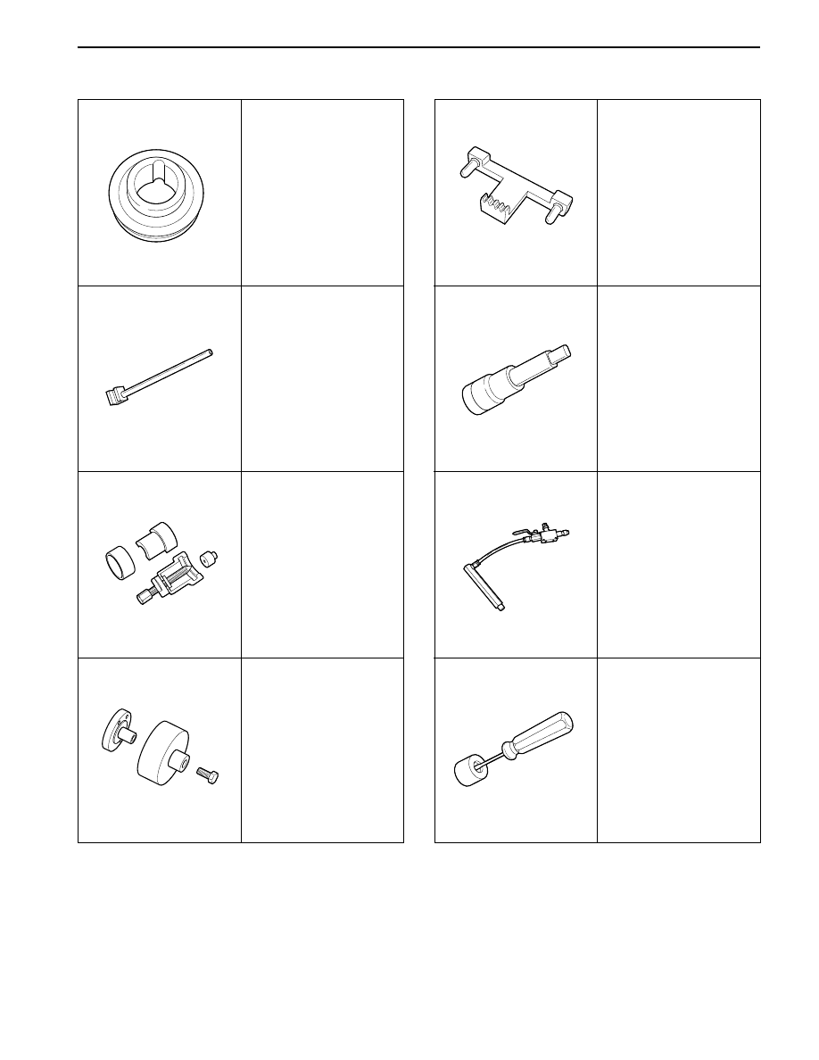
Special Tools Table (Cont’d)
615 589 01 33 00
Crankshaft Sprocket
Puller
601 589 03 43 00
Crankshaft Rear Seal
Installer
601 589 03 14 00
Crankshaft Front Seal
Installer
603 589 00 40 00
Fan Clutch Holder
DW110 - 090
Connecting Hose
DW110 - 100
Valve Tappet Remover
602 589 00 40 00
Engine Lock
617 589 00 10 00
Allen Wrench Socket
YAD1B790
YAD1B720
YAD1B4K0
YAD1B560
YAD1B2M0
YAD1B0Z0
YAD1B730
YAD1B1A0