SsangYong Rexton. Service manual - part 54


  Index      SsangYong     SsangYong Rexton - service and repair manual


Search            


Content   ..  52  53  54  55   ..


SsangYong Rexton. Service manual - part 54


DI04-29

CHANGED BY

EFFECTIVE DATE

AFFECTED VIN

EXHAUST SYSTEM

DI ENG SM - 2004.4

Y220_04026

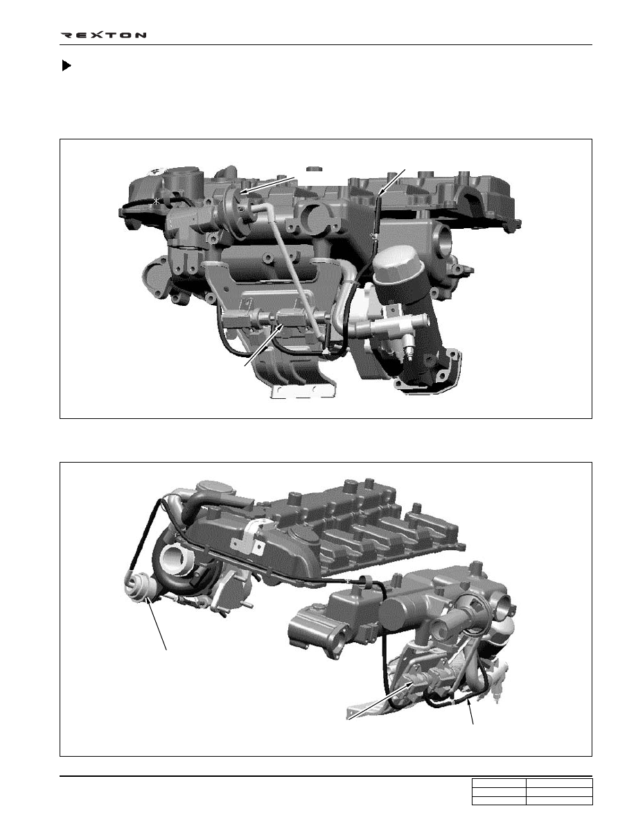
Vacuum Modulator and Vacuum Hose

Below figures illustrate vacuum hoses and related parts of EGR or turbo where wrong or poor connection of vacuum hose
would display condition of engine irregularity and defect diagnostic codes on the scan tool.

Related with EGR valve

Y220_04027

Related with turbo charger actuator

EGR valve

From vacuum pump

Vacuum modulator for

EGR valve control

Turbo charger pressure valve

Vacuum modulator for turbo

charger booster control

From vacuum pump

DI04-30

CHANGED BY

EFFECTIVE DATE

AFFECTED VIN

EXHAUST SYSTEM

DI ENG SM - 2004.4

EGR System Diagram

EGR Valve

EGR valve recirculates some of exhaust gases to intake system to reduce toxic NOx from engine according to ECU
signals.

• EGR valve opening point : -270 mmHg

EGR Modulator

According to ECU signals, the vacuum modulator drives EGR valve by controlling vacuum pressure that is generated by
vacuum pump with PWM type controls.

Y220_04028

Intercooler

Exhaust

manifold

Intake

manifold

EGR

valve

Regulated

vacuum

pressure

Modulator

Vacuum

pump

Duty

control

Feedback EGR

(Air Mass)

ECU

Improved target EGR

Air intake signal

(for EGR feed-

back control)

Turbo charger

Pedal

signal

RPM

signal

DI04-31

CHANGED BY

EFFECTIVE DATE

AFFECTED VIN

EXHAUST SYSTEM

DI ENG SM - 2004.4

Y220_04029

Operation Principle of Vacuum Modulator

According to ECU signals, the solenoid valve controls the vacuum pressure that is generated by vacuum pump (-900 

±

20 mbar) with PWM type control and drives the mechanical EGR valve and turbo charger.

Vacuum pump

Output vacuum

ATM

Plunger

Connector

Diaphragm

Vacuum control

Seat assembly
Spring

Atmospheric pressure

Plunger

Air flow

During duty increase (B)

During duty reduction (C)

Vacuum is controlled according to relationship between chamber pressure (I) in rolling nipple cover and magnetic
force (II) in plunger.

DI04-32

CHANGED BY

EFFECTIVE DATE

AFFECTED VIN

EXHAUST SYSTEM

DI ENG SM - 2004.4

Y220_04032

Y220_04031

Y220_04030

Operating principle: Balance between original vacuum pressure and magnetic force (see above figure)

• Normal state (Fig. A): Original vacuum and seat section, 3 stoppers keep sealing

• Duty up state (Fig. B): Original vacuum pressure is connected to inside of diaphragm chamber

• Duty down state (Fig. C): Increased diaphragm chamber pressure is connected to atmosphere to compensate the

pressure.

 Operating principles when duty is applied from 0 to 50 %

Vacuum consumption: Compared to 50 % of duty, ON/OFF periods are most unstable and vacuum
consumption is most high.

Output Characteristics

Floating plunger

DUTY 50%

Output C/V

Stroke

(mm)

Max. Distance 

 1mm

Flowing

volume

Output vacuum (-mmHg)

Up

Down


Content   ..  52  53  54  55   ..