SsangYong Rexton. Service manual - part 53


  Index      SsangYong     SsangYong Rexton - service and repair manual


Search            


Content   ..  51  52  53  54   ..


SsangYong Rexton. Service manual - part 53


DI04-25

CHANGED BY

EFFECTIVE DATE

AFFECTED VIN

EXHAUST SYSTEM

DI ENG SM - 2004.4

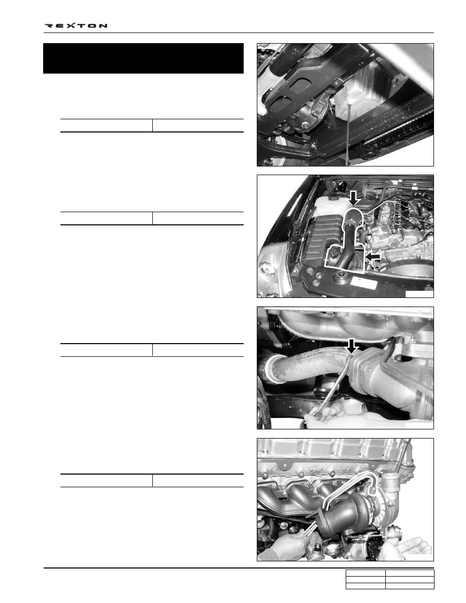
1. Remove the drain plug and drain the engine oil from the

oil pan.

Installation Notice

Y220_04018

Y220_04017

Y220_04016

Y220_04015

Turbo Charger Assembly
- Removal and Installation

2. Remove the vacuum hose and inlet hose from the turbo

charger.

Installation Notice

3. Remove the bolts and nuts at the exhaust manifold in

turbo charger.

Installation Notice

4. Remove the lower and upper bolts at turbo charger oil

supply pipe.

Installation Notice

Tightening torque

25 

± 2.5 Nm

Tightening torque

6 ~ 7 Nm

Tightening torque

25 

± 2.5 Nm

Tightening torque

23 

± 2.3 Nm

DI04-26

CHANGED BY

EFFECTIVE DATE

AFFECTED VIN

EXHAUST SYSTEM

DI ENG SM - 2004.4

Y220_04022

Y220_04021

Y220_04020

Y220_04019

5. Remove the lower bolts at turbo charger oil return pipe.

Notice

Replace the steel gasket with new one.

Tightening torque

25 

± 2.5 Nm

6. Remove the lower bolt at turbo charger bracket.

7. Remove the turbo charger bracket bolts.

Installation Notice

Tightening torque

32 

± 3.2 Nm

Notice

Use only 12 1/2" wrench.

8. Remove the bolts and nuts at the turbo charger and the

exhaust manifold.

Installation Notice

Tightening torque

25 

± 2.5 Nm

9. Remove the turbo charger assembly.

10. Install in the reverse order of removal.

Notice

• Replace the steel gasket with new one.

• To prevent gas leaks, tighten the fasteners with the

specified tightening torques.

Installation Notice

DI04-27

CHANGED BY

EFFECTIVE DATE

AFFECTED VIN

EXHAUST SYSTEM

DI ENG SM - 2004.4

Y220_04023

EGR VALVE AND VACUUM MODULATOR

1. EGR valve

2. Vacuum modulator

3. Vacuum pump

4. EGR center pipe (EGR cooler)

5. Intake manifold

6. Hfm sensor

EGR SYSTEM

General Information

EGR system controls the opening vale of EGR valve by transmitting electrical signal (PWM control) from the engine
ECU to vacuum modulator. Also, the engine ECU receives the feedback signals of the amount of air flowing through the
HFM sensor.

Various sensor

Signals

DI04-28

CHANGED BY

EFFECTIVE DATE

AFFECTED VIN

EXHAUST SYSTEM

DI ENG SM - 2004.4

Y220_04024

EGR VALVE AND TURBO CHARGER ACTUATOR CONTROL VACUUM
CIRCUIT

Vacuum Modulator

The biggest difference between the vacuum circuit and layout of the Hoover EGR system after K2004 has been intro-
duced is the location of the vacuum modulator for EGR valve control and the function of the other modulator. In case of
EGR equipped vehicle (IDI Engine), it performs the role of controlling the PLA of injection pump whereas, in DI engine, it
controls the turbo charger actuator.

DI engine vacuum modulator

1. EGR valve vacuum modulator

2. Turbo charger booster vacuum modulator

Y220_04025

2. Vacuum modulator for injection pump PLA control

IDI engine vacuum modulator (hoover EGR system - K2004)

1. Vacuum modulator for EGR valve control

To EGR valve

From vacuum pump

To PLA (injection pump)

From vacuum pump

From vacuum pump

To EGR Valve

Vacuum pump

To turbo charger

actuator


Content   ..  51  52  53  54   ..