Nissan Versa Sedan. Instruction - part 887


  Index      Nissan     Nissan Versa Sedan (2014 year) - Service and Repair Instruction


Search            copyright infringement  


Content   ..  885  886  887  888   ..


Nissan Versa Sedan. Instruction - part 887


TM-454

< UNIT REMOVAL AND INSTALLATION >

[CVT: RE0F11A]

TRANSMISSION ASSEMBLY

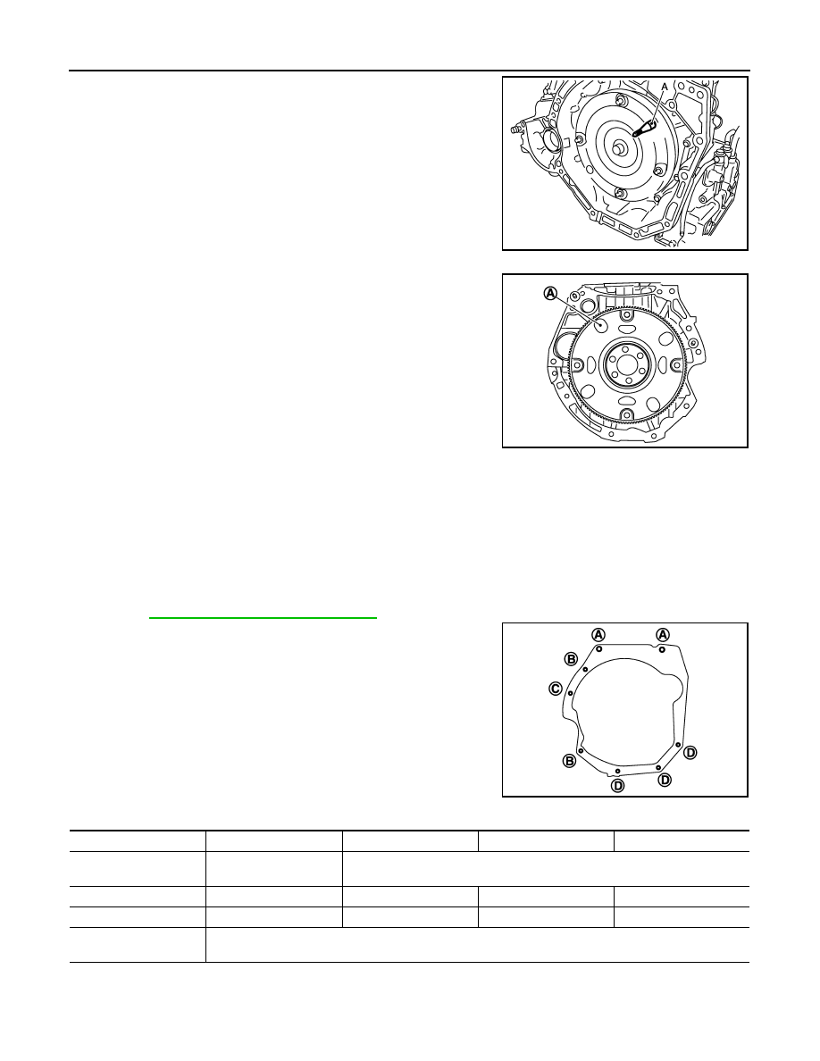
• When using suitable tool (A) for alignment, install it to the align-

ment stud bolt used to align the torque converter to the drive plate.

• Rotate the crankshaft so that the alignment hole (A) of drive plate

aligns with the position of the torque converter alignment stud bolt.

CAUTION:

• Rotate the crankshaft clockwise (as viewed from the front of

the engine).

• Be careful that torque converter stud bolts are aligned to the

drive plate holes. Otherwise the stud bolts contact the drive

plate.

• Insert the alignment stud bolt of torque converter into the align-

ment hole of the drive plate, aligning the drive plate holes with the

torque converter stud bolts.

CAUTION:

Be careful not to strike the drive plate with the torque converter stud bolts.

• When installing the torque converter nuts, temporarily tighten the nuts. Then, after installing the engine and

transaxle assembly bolts tighten the nuts to the specified torque.

CAUTION:

• Rotate the crankshaft clockwise (as viewed from the front of the engine).

• Check the tightening torque for the crankshaft pulley bolts after the bolts fastening the drive plate

and torque converter have been tightened and the crankshaft pulley bolts have been secured.

Refer to 

EM-47, "Removal and Installation"

.

• Install the transaxle assembly and engine assembly bolts accord-

ing to the following standards.

Inspection and Adjustment

INFOID:0000000009268282

INSPECTION BEFORE INSTALLATION

JPDIA0683ZZ

Tightening torque

: 51 N·m (5.2 kg-m, 38 ft-lb)

JPDIA0684ZZ

JSDIA1839ZZ

Bolt position

A

B

C

D

Direction of insertion

Transaxle assembly 

⇒ 

Engine assembly

Engine assembly 

⇒ Transaxle assembly

Quantity

2

2

1

3

Nominal length [mm (in)]

40 (1.57)

44 (1.73)

69 (2.72)

49 (1.93)

Tightening torque
N·m (kg-m, ft-lb)

48.0 (4.9, 35)

TRANSMISSION ASSEMBLY

TM-455

< UNIT REMOVAL AND INSTALLATION >

[CVT: RE0F11A]

C

E

F

G

H

I

J

K

L

M

A

B

TM

N

O

P

Check the distance (A) between the converter housing and torque

converter.

INSPECTION AFTER INSTALLATION

Check the following items:

• For CVT position, refer to 

TM-430, "Inspection and Adjustment"

.

• Before starting engine, check oil/fluid levels including engine coolant and engine oil. If less than required

quantity, fill to the specified level. Refer to 

MA-12, "Fluids and Lubricants"

.

• Use procedure below to check for fuel leakage.

• Turn ignition switch ON (with engine stopped). With fuel pressure applied to fuel piping, check for fuel leak-

age at connection points.

• Start engine. With engine speed increased, check again for fuel leakage at connection points.

• Run engine to check for unusual noise and vibration.

NOTE:

If hydraulic pressure inside timing chain tensioner drops after removal and installation, slack in the guide

may generate a pounding noise during and just after engine start. However, this is normal. Noise will stop

after hydraulic pressure rises.

• Warm up engine thoroughly to make sure there is no leakage of fuel, exhaust gas, or any oils/fluids including

engine oil and engine coolant.

• Bleed air from passages in lines and hoses, such as in cooling system.

• After cooling down engine, again check oil/fluid levels including engine oil and engine coolant. Refill to spec-

ified level, if necessary.

• Summary of the inspection items:

*Power steering fluid, brake fluid, etc.

ADJUSTMENT AFTER INSTALLATION

• Adjust the CVT fluid level. 

TM-427, "Adjustment"

.

• Perform "ADDITIONAL SERVICE WHEN REPLACING TRANSAXLE ASSEMBLY". Refer to 

TM-326,

"Description"

.

B

:  Scale

C

: Straightedge

Dimension (A)

TM-457, "Torque Converter"

JSDIA1840ZZ

Item

Before starting engine

Engine running

After engine stopped

Engine coolant

Level

Leakage

Level

Engine oil

Level

Leakage

Level

Transmission/
transaxle fluid 

A/T and CVT Models

Leakage

Level/Leakage

Leakage

M/T Models

Level/Leakage

Leakage

Level/Leakage

Other oils and fluids*

Level

Leakage

Level

Fuel

Leakage

Leakage

Leakage

Exhaust gas

Leakage

TM-456

< SERVICE DATA AND SPECIFICATIONS (SDS) 

[CVT: RE0F11A]

SERVICE DATA AND SPECIFICATIONS (SDS)

SERVICE DATA AND SPECIFICATIONS (SDS)

SERVICE DATA AND SPECIFICATIONS (SDS)

General Specification

INFOID:0000000009268283

*1: Refer to 

MA-12, "Fluids and Lubricants"

.

*2: The CVT fluid capacity is the reference value. 

Shift Characteristics

INFOID:0000000009268284

Unit: rpm

CAUTION:

Lock-up is engaged at the vehicle speed of approximately 10 km/h (11 MPH) to 90 km/h (56 MPH). 

Stall Speed

INFOID:0000000009268285

Unit: rpm

Line Pressure

INFOID:0000000009268286

Unit: MPa (kg/cm

2

, psi)

Transaxle model

RE0F11A

Stall torque ratio

1.91 : 1

Pulley ratio

Forward

2.200 – 0.550

Reverse

2.200

Auxiliary gearbox gear ratio

1GR

1.821

2GR

1.000

Reverse

1.714

Counter gear

0.967

Final drive

3.882

Recommended fluid

Genuine NISSAN CVT Fluid NS-3

*1

Fluid capacity

Approx. 6.9 liter (7-1/4 US qt, 6-1/8 Imp qt)

*2

CAUTION:

• Use only Genuine NISSAN CVT Fluid NS-3. Do not mix with other fluid.
• Use only Genuine NISSAN CVT Fluid NS-3. Using transmission fluid other than Genuine NISSAN CVT Fluid NS-3 will dam-

age the CVT, which is not covered by the (NISSAN new vehicle limited) warranty.

 Throttle position

Shift pattern

Engine speed

At 40 km/h (25 MPH)

At 60 km/h (37 MPH)

2/8

“D” position (Overdrive control OFF)

1,400 – 2,700

1,500 – 3,100

“D” position (Overdrive control ON)

1,500 – 2,700

2,400 – 3,200

“L” position

2,800 – 3,600

3,800 – 4,600

8/8

“D” position (Overdrive control OFF)

3,900 – 4,700

4,500 – 5,300

“D” position (Overdrive control ON)

3,900 – 4,700

4,500 – 5,300

“L” position

3,900 – 4,700

4,500 – 5,300

Stall speed

2,400 – 2,770

Shift selector position

Engine speed

Line pressure

“P” and “N”

At idle

0.50 (5.1, 72.5)

“R” and “D”

At idle

0.50 (5.1, 72.5) – 1.51 (15.4, 219)

At stall

4.93 (50.3, 714.9) – 5.43 (55.4, 787.4)

SERVICE DATA AND SPECIFICATIONS (SDS)

TM-457

< SERVICE DATA AND SPECIFICATIONS (SDS) 

[CVT: RE0F11A]

C

E

F

G

H

I

J

K

L

M

A

B

TM

N

O

P

Torque Converter

INFOID:0000000009268287

Heater Thermostat

INFOID:0000000009268288

Standard

Reference value

Distance (A) between the converter housing and torque converter

16.2 mm

Valve lift

More than 5.0 mm (0.197 in)

Valve opening temperature

71

°C (160°F)

Minimum valve lift

5.0 mm/85

°C (0.197 in/203°F)


Content   ..  885  886  887  888   ..