Nissan Versa Sedan. Instruction - part 877


  Index      Nissan     Nissan Versa Sedan (2014 year) - Service and Repair Instruction


Search            copyright infringement  


Content   ..  875  876  877  878   ..


Nissan Versa Sedan. Instruction - part 877


TM-414

< DTC/CIRCUIT DIAGNOSIS >

[CVT: RE0F11A]

MAIN POWER SUPPLY AND GROUND CIRCUIT

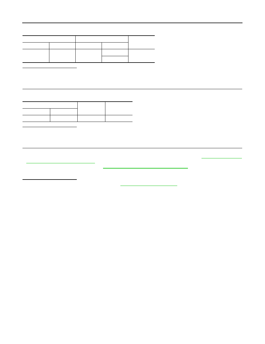
3. Check continuity between IPDM E/R harness connector terminal and TCM harness connector terminals.

Is the check result normal?

YES

>> GO TO 6.

NO

>> Repair or replace  malfunctioning parts.

6.

CHECK CIRCUIT BETWEEN IPDM E/R AND TCM (PART 2)

Check continuity between IPDM E/R harness connector terminal and ground. 

Is the check result normal?

YES

>> GO TO 7.

NO

>> Repair or replace  malfunctioning parts.

7.

DETECT MALFUNCTIONING ITEMS (PART 2)

Check the following items:

• Harness open circuit or short circuit between  ignition switch and IPDM E/R. Refer to 

PG-20, "Wiring Dia-

gram — Ignition Power Supply —"

.

• 10A fuse (No.49, IPDM E/R). Refer to 

PG-62, "IPDM E/R Terminal Arrangement"

.

• IPDM E/R
Is the check result normal?

YES

>> Check intermittent incident. Refer to 

GI-45, "Intermittent Incident"

.

NO

>> Repair or replace  malfunctioning parts.

IPDM E/R harness connector

TCM harness connector 

Continuity

Connector

Terminal

Connector

Terminal

E45

21

F44

47

Existed

48

IPDM E/R harness connector

Ground

Continuity

Connector

Terminal

E45

21

Ground

Not existed

OVERDRIVE CONTROL SWITCH

TM-415

< DTC/CIRCUIT DIAGNOSIS >

[CVT: RE0F11A]

C

E

F

G

H

I

J

K

L

M

A

B

TM

N

O

P

OVERDRIVE CONTROL SWITCH

Component Function Check

INFOID:0000000009268230

1.

CHECK OD OFF INDICATOR LAMP FUNCTION

Check OD OFF indicator lamp turns ON for approx. 2 seconds when ignition switch turns ON.
Is the inspection results normal?

YES

>> GO TO 2.

NO

>> Go to 

TM-417, "Diagnosis Procedure"

.

2.

CHECK OVERDRIVE CONTROL SWITCH FUNCTION

1. Shift the selector lever to “D” position.

2. Check that OD OFF indicator lamp turns ON/OFF when overdrive control switch is operated.
Is the inspection results normal?

YES

>> INSPECTION END

NO

>> Go to 

TM-415, "Diagnosis Procedure"

.

Diagnosis Procedure

INFOID:0000000009268231

1.

CHECK OVERDRIVE CONTROL SWITCH CIRCUIT 

1. Turn ignition switch OFF.

2. Disconnect CVT shift selector connector.

3. Turn ignition switch ON.

4. Check  voltage between CVT shift selector harness connector terminals.

Is the inspection result normal?

YES

>> GO TO 2.

NO

>> GO TO 4.

2.

CHECK OVERDRIVE CONTROL SWITCH

Check overdrive control switch. Refer to 

TM-416, "Component Inspection (Overdrive Control Switch)"

.

Is the inspection result normal?

YES

>> GO TO 3.

NO

>> Repair or replace  malfunctioning parts.

3.

CHECK GROUND CIRCUIT

Check  continuity between CVT shift selector harness connector terminal and ground.

Is the inspection result normal?

YES

>> GO TO 4.

NO

>> Repair or replace  malfunctioning parts.

4.

CHECK CIRCUIT BETWEEN COMBINATION METER AND CVT SHIFT SELECTOR (PART 1)

1. Turn ignition switch OFF.

2. Disconnect combination meter connector.

3. Check  continuity between combination meter harness connector terminal and CVT shift selector harness

connector terminal.

CVT shift selector

Voltage

Connector

+

Terminal

M38

1

2

Approx. 5 V

CVT shift selector

Ground

Continuity

Connector

Terminal

M38

2

Ground

Existed

TM-416

< DTC/CIRCUIT DIAGNOSIS >

[CVT: RE0F11A]

OVERDRIVE CONTROL SWITCH

*1: TYPE A (Refer to 

MWI-55, "Information"

.)

*2: TYPE B (Refer to 

MWI-5, "Information"

.)

Is the inspection result normal?

YES

>> GO TO 5.

NO

>> Repair or replace  malfunctioning parts.

5.

CHECK CIRCUIT BETWEEN COMBINATION METER AND CVT SHIFT SELECTOR (PART 2)

Check  continuity between combination meter harness connector terminal and ground.

*1: TYPE A (Refer to 

MWI-55, "Information"

.)

*2: TYPE B (Refer to 

MWI-5, "Information"

.)

Is the inspection result normal?

YES

>> GO TO 6.

NO

>> Repair or replace  malfunctioning parts.

6.

CHECK COMBINATION METER INPUT SIGNAL

1. Connect all of  disconnected connectors.

2. Turn ignition switch ON.

3. Select “Data Monitor” in “METER/M&A”.

4. Select “O/D OFF SW”.

5. Check that “O/D OFF SW” turns ON/OFF when overdrive control switch is operated. Refer to 

MWI-22,

"Reference Value"

.

Is the inspection result normal?

YES

>> Check intermittent incident. Refer to 

GI-45, "Intermittent Incident"

.

NO

>> Replace combination meter. Refer to 

MWI-53, "Removal and Installation"

.

Component Inspection (Overdrive Control Switch)

INFOID:0000000009268232

1.

CHECK OVERDRIVE CONTROL SWITCH

Check  continuity between wires of selector lever knob (1)

Is the inspection result normal?

YES

>> INSPECTION END

NO

>> Replace  selector lever knob. Refer to 

TM-429,

"Removal and Installation"

.

Combination meter

CVT shift selector

Continuity

Connector

Terminal

Connector

Terminal

M82

*1

8

M38

1

Existed

M24

*2

28

Existed

Combination meter

Ground

Continuity

Connector

Terminal

M82

*1

8

Ground

Not existed

M24

*2

28

Condition

Continuity

Overdrive control switch is depressed

Existed

Overdrive control switch is depressed

Not existed

JSDIA1969ZZ

OD OFF INDICATOR LAMP

TM-417

< DTC/CIRCUIT DIAGNOSIS >

[CVT: RE0F11A]

C

E

F

G

H

I

J

K

L

M

A

B

TM

N

O

P

OD OFF INDICATOR LAMP

Component Function Check

INFOID:0000000009268233

1.

CHECK OD OFF INDICATOR LAMP FUNCTION

Check OD OFF indicator lamp turns ON for approx. 2 seconds when ignition switch turns ON.
Is the inspection results normal?

YES

>> INSPECTION END

NO

>> Go to 

TM-417, "Diagnosis Procedure"

.

Diagnosis Procedure

INFOID:0000000009268234

1.

CHECK DTC (TCM)

With CONSULT

1. Turn ignition switch ON.

2. Check “Self Diagnostic Results” in “TRANSMISSION”.
Is any DTC detected?

YES

>> Check DTC detected item. Refer to 

TM-311, "DTC Index"

.

NO

>> GO TO 2.

2.

CHECK DTC (COMBINATION METER)

With CONSULT

Check “Self Diagnostic Results” in “METER/M&A”.
Is any DTC detected?

YES

>> Check DTC detected item. Refer to 

MWI-25, "DTC Index"

.

NO

>> GO TO 3.

3.

CHECK COMBINATION METER INPUT SIGNAL

With CONSULT

1. Shift the selector lever to “D” position.

2. Select “Data Monitor” in “METER/M&A”.

3. Select “O/D OFF IND”.

4. Check that “O/D OFF IND” turns ON/OFF when overdrive control switch is operated. Refer to 

MWI-22,

"Reference Value"

.

Is the inspection result normal?

YES

>> Replace combination meter. Refer to 

MWI-53, "Removal and Installation"

.

NO

>> GO TO 4.

4.

CHECK TCM INPUT/OUTPUT SIGNAL

With CONSULT

1. Select “Data Monitor” in “TRANSMISSION”.

2. Select “SPORT MODE SW”.

3. Check that “SPORT MODE SW” turns ON/OFF when overdrive control switch is operated. Refer to 

TM-

299, "Reference Value"

.

Is the inspection result normal?

YES

>> Replace combination meter. Refer to 

MWI-53, "Removal and Installation"

.

NO

>> Check overdrive control switch. Refer to 

TM-415, "Diagnosis Procedure"

.


Content   ..  875  876  877  878   ..