Nissan Versa Sedan. Instruction - part 513
INL-48
< DTC/CIRCUIT DIAGNOSIS >
PUSH-BUTTON IGNITION SWITCH ILLUMINATION CIRCUIT
YES
>> GO TO 3.
NO
>> Repair or replace the harness or connectors.
3.
CHECK PUSH-BUTTON IGNITION SWITCH ILLUMINATION POWER SUPPLY SHORT CIRCUIT
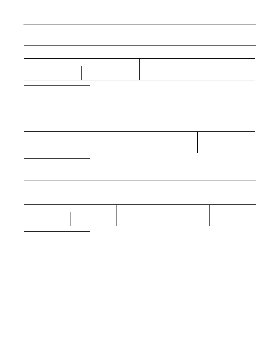
Check continuity between BCM connector M98 terminal 90 and ground.
Is the inspection result normal?
YES
>> Replace BCM. Refer to
BCS-69, "Removal and Installation"
NO
>> Repair or replace the harness or connectors.
4.
CHECK PUSH-BUTTON IGNITION SWITCH ILLUMINATION GROUND CIRCUIT
1. Turn the ignition switch OFF
2. Disconnect push-button ignition switch connector.
3. Check continuity between push-button ignition switch connector M25 terminal 6 and ground.
Is the inspection result normal?
YES
>> Replace push-button ignition switch. Refer to
PCS-100, "Removal and Installation"
.
NO
>> GO TO 5.
5.
CHECK PUSH-BUTTON IGNITION SWITCH ILLUMINATION GROUND OPEN CIRCUIT
1. Disconnect BCM connector M98.
2. Check continuity between BCM connector M98 terminal 92 and push-button ignition switch connector
M25 terminal 6.
Is the inspection result normal?
YES
>> Replace BCM. Refer to
BCS-69, "Removal and Installation"
NO
>> Repair or replace the harness or connectors.
BCM
Ground
Continuity
Connector
Terminal
M98
90
No
Push-button ignition switch
Ground
Continuity
Connector
Terminal
M25
6
Yes
BCM
Push-button ignition switch
Continuity
Connector
Terminal
Connector
Terminal
M98
92
M25
6
Yes