Nissan Versa Sedan. Instruction - part 511


  Index      Nissan     Nissan Versa Sedan (2014 year) - Service and Repair Instruction


Search            copyright infringement  


Content   ..  509  510  511  512   ..


Nissan Versa Sedan. Instruction - part 511


INL-40

< DTC/CIRCUIT DIAGNOSIS >

POWER SUPPLY AND GROUND CIRCUIT

1.

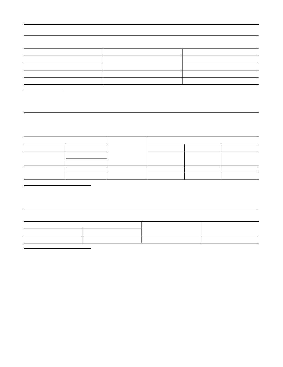
CHECK FUSES AND FUSIBLE LINK

Check that the following fuses and fusible link are not blown.

Is the fuse blown?

YES

>> Replace the blown fuse or fusible link after repairing the affected circuit.

NO

>> GO TO 2.

2.

CHECK POWER SUPPLY CIRCUIT

1. Turn ignition switch OFF.

2. Disconnect BCM connectors.

3. Check voltage between BCM connector and ground.

Is the inspection result normal?

YES

>> GO TO 3.

NO

>> Repair harness or connector.

3.

CHECK GROUND CIRCUIT

Check continuity between BCM connector and ground.

Is the inspection result normal?

YES

>> Inspection End.

NO

>> Repair harness or connector.

Terminal No.

Signal name

Fuses and fusible link No.

57

Battery power supply

12 (10A)

70

G (40A)

11

Ignition switch ACC or ON

18 (10A)

38

Ignition switch ON or START

2 (10A)

BCM

Ground

Ignition switch position

Connector

Terminal

OFF

ACC

ON

M20

57

Battery voltage

Battery voltage

Battery voltage

70

M18

11

0 V

Battery voltage

Battery voltage

38

0 V

0 V

Battery voltage

BCM

Ground

Continuity

Connector

Terminal

M20

67

Yes

BATTERY SAVER OUTPUT/POWER SUPPLY CIRCUIT

INL-41

< DTC/CIRCUIT DIAGNOSIS >

C

D

E

F

G

H

I

J

K

M

A

B

INL

N

O

P

BATTERY SAVER OUTPUT/POWER SUPPLY CIRCUIT

Description

INFOID:0000000009269246

Provides the battery saver output/power supply. Also cuts the power supply when the interior lamp battery

saver is activated.

Component Function Check

INFOID:0000000009269247

1.

CHECK BATTERY SAVER OUTPUT/POWER SUPPLY FUNCTION

CONSULT

1. Turn ignition switch ON.

2. Turn each interior lamp to the ON position.

-

Interior room lamp

-

Map lamp (if equipped)

-

Trunk room lamp

3. Select BATTERY SAVER of BCM (BATTERY SAVER) active test item.

4. While operating the test item, check that each interior room lamp turns ON/OFF.

Is the inspection result normal?

YES

>> Battery saver output/power supply circuit is normal.

NO

>> Refer to 

INL-41, "Diagnosis Procedure"

.

Diagnosis Procedure

INFOID:0000000009269248

Regarding Wiring Diagram information, refer to 

INL-22, "Wiring Diagram"

.

1.

CHECK BATTERY SAVER OUTPUT/POWER SUPPLY OUTPUT

CONSULT

1. Turn ignition switch ON.

2. Select BATTERY SAVER of BCM (BATTERY SAVER) active test item.

3. While operating the test item, check voltage between BCM connector and ground.

Is the inspection result normal?

YES

>> GO TO 2.

NO

>> Replace BCM after making sure battery saver output/power supply circuit is not shorted to volt-

age. Refer to 

BCS-69, "Removal and Installation"

 (with Intelligent Key) or 

BCS-122, "Removal

and Installation"

 (without Intelligent Key).

2.

CHECK BATTERY SAVER OUTPUT/POWER SUPPLY OPEN CIRCUIT

1. Turn ignition switch OFF.

2. Disconnect the following connectors.

-

BCM 

-

Interior room lamp

-

Map lamp (if equipped)

-

Trunk room lamp 

3. Check continuity between BCM connector and each interior lamp connector.

OFF

: Interior room lamp OFF

ON

: Interior room lamp ON

(+)

(-)

Test item

Voltage

Connector

Terminal

BATTERY SAVER

M99 (with Intelligent Key)

M20 (without Intelligent Key)

56

Ground

OFF

0V

ON

Battery voltage

INL-42

< DTC/CIRCUIT DIAGNOSIS >

BATTERY SAVER OUTPUT/POWER SUPPLY CIRCUIT

Is the inspection result normal?

YES

>> GO TO 3.

NO

>> Repair or replace the harness or connector.

3.

CHECK BATTERY SAVER OUTPUT/POWER SUPPLY SHORT CIRCUIT

Check continuity between BCM connector and ground.

Is the inspection result normal?

YES

>> Check that each interior room lamp has no internal short circuit.

NO

>> Repair or replace the harness or connector.

BCM

Each interior lamp

Continuity

Connector

Terminal

Connector

Terminal

M99 (with Intelligent Key)

M20 (without Intelligent Key)

56

Interior room lamp

R7

2

Yes

Map lamp (if equipped)

R2

1

Trunk room lamp 

B21

1

Connector

Terminal

Continuity

M99 (with Intelligent Key)

M20 (without Intelligent Key)

56

Ground

No

INTERIOR ROOM LAMP CONTROL CIRCUIT

INL-43

< DTC/CIRCUIT DIAGNOSIS >

C

D

E

F

G

H

I

J

K

M

A

B

INL

N

O

P

INTERIOR ROOM LAMP CONTROL CIRCUIT

Description

INFOID:0000000009269249

Controls each interior room lamp (ground side) by PWM signal.

NOTE:

PWM signal control period is approximately 250 Hz (in the gradual brightening/dimming).

Component Function Check

INFOID:0000000009269250

CAUTION:

 Before performing the diagnosis, check that the following are normal.

• Interior room lamp power supply

• Map lamp bulb

• Room lamp bulb

1.

CHECK INTERIOR ROOM LAMP CONTROL FUNCTION

CONSULT

1. Switch the map lamp switch or interior room lamp switch to DOOR.

2. Turn ignition switch ON.

3. Select INT LAMP of BCM (INT LAMP) ACTIVE TEST item.

4. While operating the test items, check that each interior room lamp turns ON/OFF.

Does the interior room lamp turns ON/OFF (gradual brightening/dimming)?

YES

>> Interior room lamp control circuit is normal.

NO

>> Refer to 

INL-43, "Diagnosis Procedure"

.

Diagnosis Procedure

INFOID:0000000009269251

Regarding Wiring Diagram information, refer to 

INL-22, "Wiring Diagram"

.

1.

CHECK INTERIOR ROOM LAMP CONTROL OUTPUT

CONSULT

1. Turn ignition switch OFF.

2. Remove all the bulbs of map lamp and interior room lamp.

3. Turn ignition switch ON.

4. Select INT LAMP of BCM (INT LAMP) ACTIVE TEST item.

5. While operating the test item, check continuity between BCM harness connector and ground.

Is the inspection result normal?

YES

>> GO TO 2.

Fixed ON>>GO TO 3.

Fixed OFF>>Replace BCM after making sure battery saver output/power supply circuit is not shorted to volt-

age. Refer to 

BCS-69, "Removal and Installation"

 (with Intelligent Key) or 

BCS-122, "Removal

and Installation"

 (without Intelligent Key).

2.

CHECK INTERIOR ROOM LAMP CONTROL OPEN CIRCUIT

1. Turn ignition switch OFF.

2. Disconnect BCM connector and map lamp connector or interior room lamp connector.

On

: Interior room lamp gradual brightening

Off

: Interior room lamp gradual dimming

BCM

Ground

Test item

Continuity

Connector

Terminal

M99 (with Intelligent Key)

M20 (without Intelligent Key)

63

INT LAMP

On

Yes

Off

No


Content   ..  509  510  511  512   ..