Nissan Versa Sedan. Instruction - part 479
DIAGNOSIS AND REPAIR WORKFLOW
HA-15
< BASIC INSPECTION >
C
D
E
F
G
H
J
K
L
M
A
B
HA
N
O
P
BASIC INSPECTION
DIAGNOSIS AND REPAIR WORKFLOW
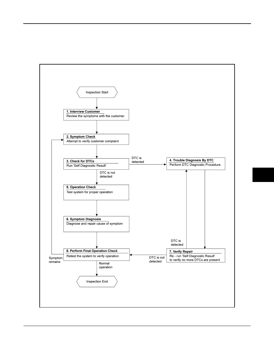
Workflow
INFOID:0000000009269736
OVERALL SEQUENCE
DETAILED FLOW
1.
INTERVIEW CUSTOMER
Interview the customer to obtain as much information as possible about the conditions and environment under
which the malfunction occurred.
ALIIA0440GB