Nissan Versa Sedan. Instruction - part 478
PREPARATION
HA-11
< PREPARATION >
C
D
E
F
G
H
J
K
L
M
A
B
HA
N
O
P
(Tool number)
Tool name
Description
(J-41810-NI)
Refrigerant identifier equipment (R-
134a)
Checking refrigerant purity and system
contamination
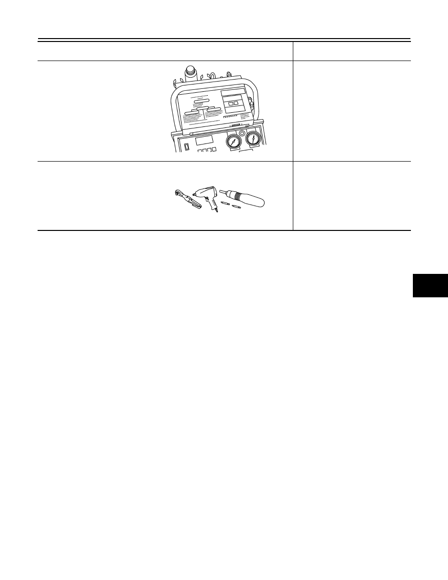
( — )
Power tool
Loosening nuts, screws and bolts
RJIA0197E
PIIB1407E