Nissan Versa Sedan. Instruction - part 477


  Index      Nissan     Nissan Versa Sedan (2014 year) - Service and Repair Instruction


Search            copyright infringement  


Content   ..  475  476  477  478   ..


Nissan Versa Sedan. Instruction - part 477


PRECAUTIONS

HA-7

< PRECAUTION >

C

D

E

F

G

H

J

K

L

M

A

B

HA

N

O

P

CAUTION:

When replacing or cleaning refrigerant cycle components, observe the following:

• When the compressor is removed, store it in the same position as it is when installed on the vehicle.

Doing so will cause oil to enter the low-pressure chamber.

• When connecting pipes, always use a torque wrench and a back-up wrench.

• After disconnecting pipes, immediately plug all openings to prevent entry of dirt and moisture.

• When installing an air conditioner in the vehicle, connect the pipes as the final stage of the opera-

tion. Do not remove the seal caps of pipes and other components until just before required for con-

nection.

• Allow components stored in cool areas to warm to working area temperature before removing seal

caps. This prevents condensation from forming inside A/C components.

• Thoroughly remove moisture from the refrigeration system before charging the refrigerant.

• Do not reuse O-rings.

• O-ring must be installed near the dented portion of pipe.

• When replacing the O-ring, be careful not to damage O-ring and pipe.

• Connect tube until you hear it click, then tighten the nut or bolt by hand until snug. Make sure that

the O-ring is installed to pipe correctly.

• After connecting pipe, perform leak test and make sure that there is no leakage from connections.

When the refrigerant leaking point is found, disconnect that line and replace the O-ring. Then tighten

connections of seal seat to the specified torque.

Service Equipment

INFOID:0000000009269727

RECOVERY/RECYCLING RECHARGING EQUIPMENT

Be certain to follow the manufacturer’s instructions for machine operation and machine maintenance. Do not

introduce any refrigerant other than that specified into the machine.

ELECTRICAL LEAK DETECTOR

Be certain to follow the manufacturer’s instructions for tester operation and tester maintenance.
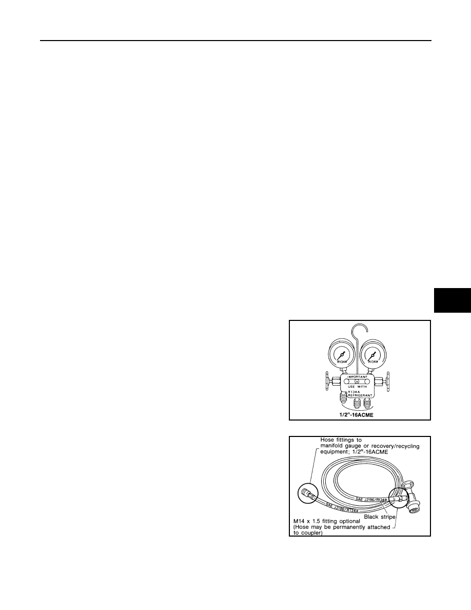
MANIFOLD GAUGE SET

Be certain that the gauge face indicates HFC-134a or R-134a. Be

sure the gauge set has 1/2

″-16 ACME threaded connections for ser-

vice hoses. Confirm the set has been used only with refrigerant

HFC-134a (R-134a) and specified oils.

SERVICE HOSES

Be certain that the service hoses display the markings described

(colored hose with black stripe). All hoses must have positive shut-

off devices (either instruction or automatic) near the end of the hoses

opposite to the manifold gauge.

SERVICE COUPLERS

SHA533D

RHA272D

HA-8

< PRECAUTION >

PRECAUTIONS

Do not attempt to connect HFC-134a (R-134a) service couplers to

the CFC-12 (R-12) A/C system. The HFC-134a (R-134a) couplers

do not properly connect to the CFC-12 (R-12) system. If an improper

connection is attempted, discharging and contamination may occur.

CHARGING CYLINDER

Using a charging cylinder is not recommended. Refrigerant may be vented into air from cylinder's top valve

when filling the cylinder with refrigerant. Also, the accuracy of the cylinder is generally less than that of an

electronic scale or of quality recycle/recharge equipment.

Shut-off valve rotation

A/C service valve

Clockwise

Open

Counterclockwise

Close

RHA273D

PREPARATION

HA-9

< PREPARATION >

C

D

E

F

G

H

J

K

L

M

A

B

HA

N

O

P

PREPARATION

PREPARATION

Special Service Tool

INFOID:0000000009269728

The actual shape of Kent-Moore tools may differ from those of special service tools illustrated here.

HFC-134a (R-134a) Service Tool and Equipment

INFOID:0000000009269729

Do not mix HFC-134a (R-134a) refrigerant and/or its specified oil with CFC-12 (R-12) refrigerant and/or its oil.

Separate and non-interchangeable service equipment must be used for handling each type of refrigerant/oil.

Refrigerant container fittings, service hose fittings and service equipment fittings (equipment which handles

refrigerant and/or oil) are different between CFC-12 (R-12) and HFC-134a (R-134a). This is to avoid mixed

use of the refrigerants/oil.

Adapters that convert one size fitting to another must not be used refrigerant/oil contamination will occur and

compressor failure will result.

Tool number
(Kent-Moore No.)
Tool name

Description

(J-41425-NIS)
Aluminum tube repair kit

Repairing leaks in A/C tubes

(J-38873-A)
Drive plate installer

Installing pulley and drive plate

ALIIA0390ZZ

WJIA0367E

Tool number
(Kent-Moore No.)
Tool name

Description 

( — )
HFC-134a (R-134a) Refrigerant

Container color: Light blue
Container marking: HFC-134a (R-
134a)
Fitting size: Thread size
• large container 1/2”-16 ACME

( — )
NISSAN A/C System Oil Type R

Type: Poly alkylene glycol oil (PAG), 
type R
Application: HFC-134a (R-134a) vane 
rotary compressors (NISSAN only)
Lubricity: 40 m  (1.4 US fl oz, 1.4 Imp 
fl oz) 

S-NT196

S-NT197

HA-10

< PREPARATION >

PREPARATION

Commercial Service Tool

INFOID:0000000009269730

(J-48710)
Nissan ACR2009 RRR Unit

Refrigerant Recovery, Recycling and 
Recharging

(J-43926)
A/C leak detection kit
Kit includes:
(J-42220)
UV lamp and UV safety goggles
(J-41459)
Refrigerant dye injector
(J-41447)
Fluorescent leak detection dye 
(box of 24, 1/4 ounce bottles)
(J-43872)
Refrigerant dye cleaner

Power supply:
• DC 12V (battery terminal)

Service hoses:
• High side hose

(J-39500-72B)

• Low side hose

(J-39500-72R)

• Utility hose

(J-39500-72Y)

Hose color:
• Low side hose: Blue with black stripe
• High side hose: Red with black stripe
• Utility hose: Yellow with black stripe 

or green with black stripe
Hose fitting to gauge:

• 1/2”-16 ACME

Service couplers
• High side coupler

(J-39500-20A)

• Low side coupler

(J-39500-24A)

Hose fitting to service hose:
• M14 x 1.5 fitting is optional or perma-

nently attached.

(J-39699)
Refrigerant weight scale

For measuring of refrigerant
Fitting size-Thread size
• 1/2”-16 ACME

(J-39649)
Vacuum pump
(Including the isolator valve)

Capacity:
• Air displacement: 4 CFM
• Micron rating: 20 microns
• Oil capacity: 482 g (17 oz)

Fitting size-Thread size

• 1/2”-16 ACME

Tool number
(Kent-Moore No.)
Tool name

Description 

WJIA0293E

ZHA200H

S-NT201

S-NT202

S-NT200

S-NT203


Content   ..  475  476  477  478   ..