Nissan Versa Sedan. Instruction - part 475
REAR REGULATOR
GW-27
< REMOVAL AND INSTALLATION >
C
D
E
F
G
H
I
J
L
M
A
B
GW
N
O
P
REAR REGULATOR
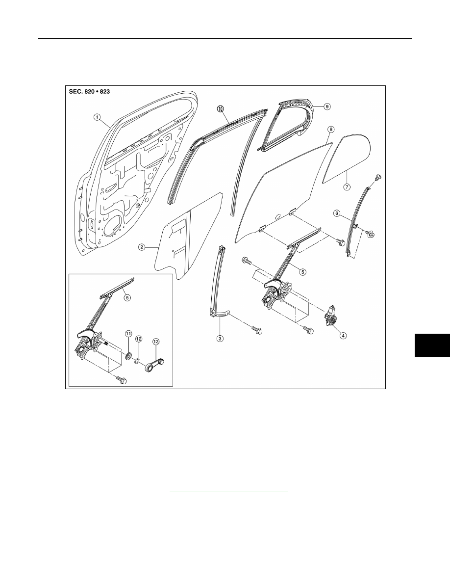
Exploded View
INFOID:0000000009267765
Removal and Installation
INFOID:0000000009267766
REMOVAL
1. Remove rear door glass. Refer to
GW-25, "Removal and Installation"
.
2. Disconnect the harness connector from rear door power window motor.
3. Remove rear door regulator assembly bolts and regulator assembly from rear door panel.
INSTALLATION
Installation is in the reverse order of removal.
1.
Rear door panel
2.
Sealing screen
3.
Rear door sash
4.
Rear power window motor
5.
Regulator assembly
6.
Partition sash
7.
Partition glass
8.
Rear door glass
9.
Partition weather-strip
10. Rear door glass run
11. Regulator seal (instruction window)
12. Retaining clip (instruction window)
13. Regulator handle (instruction window)
AWKIA1882ZZ