Nissan Versa Sedan. Instruction - part 393


  Index      Nissan     Nissan Versa Sedan (2014 year) - Service and Repair Instruction


Search            copyright infringement  


Content   ..  391  392  393  394   ..


Nissan Versa Sedan. Instruction - part 393


CYLINDER BLOCK

EM-107

< UNIT DISASSEMBLY AND ASSEMBLY >

[HR16DE]

C

D

E

F

G

H

I

J

K

L

M

A

EM

N

P

O

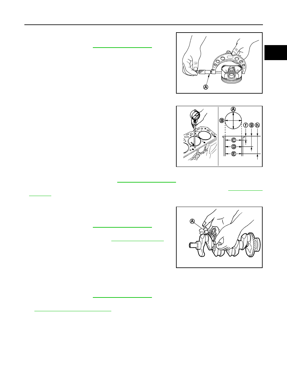
Piston Skirt Diameter

Measure the outer diameter of piston skirt with a suitable tool (A).

Piston to Cylinder Bore Clearance

Calculate by piston skirt diameter and cylinder bore inner diameter

[direction (B), position (D)].

(Clearance) = (Cylinder bore inner diameter) – (Piston skirt diame-

ter)

• If it exceeds the limit, replace piston and piston pin assembly and/or cylinder block. Refer to 

EM-122, "Cylin-

der Block"

.

CRANKSHAFT MAIN JOURNAL DIAMETER

• Measure the outer diameter of crankshaft main journals with a suit-

able tool (A).

• If out of the standard, measure the main bearing oil clearance.

Then use undersize bearing. Refer to 

EM-125, "Main Bearing"

.

CRANKSHAFT PIN JOURNAL DIAMETER 

• Measure the outer diameter of crankshaft pin journal with a suitable tool.

• If out of the standard, measure the connecting rod bearing oil clearance. Then use undersize bearing. Refer

to 

EM-126, "Connecting Rod Bearing"

.

OUT-OF-ROUND AND TAPER OF CRANKSHAFT

Standard : 

Refer 

to 

EM-122, "Cylinder Block"

.

PBIC3272J

(A)

: Direction A

(C)

: Position C

(E)

: Position E

(f)

: 10 mm (0.39 in)

(g)

: 60 mm (2.36 in)

(h)

: 124 mm (4.88 in)

Standard and Limit 

: Refer to 

EM-122, "Cylinder Block"

.

JPBIA2059ZZ

Standard : 

Refer 

to 

EM-122, "Cylinder Block"

.

PBIC3457J

Standard : 

Refer 

to 

EM-122, "Cylinder Block"

.

EM-108

< UNIT DISASSEMBLY AND ASSEMBLY >

[HR16DE]

CYLINDER BLOCK

• Measure the dimensions at four different points as shown on each

main journal and pin journal with a suitable tool. 

• Out-of-round is indicated by the difference in dimensions between

(a) and (b) at (c) and (d).

• Taper is indicated by the difference in dimension between (c) and

(d) at (a) and (b).

• If the measured value exceeds the limit, correct or replace crankshaft.

• If corrected, measure the bearing oil clearance of the corrected main journal and/or pin journal. Then select

main bearing and/or connecting rod bearing. Refer to 

EM-126, "Connecting Rod Bearing"

 and/or 

EM-125,

"Main Bearing"

.

CRANKSHAFT RUNOUT 

• Place a V-block on a precise flat table to support the journals on both ends of the crankshaft.

• Place a suitable tool (A) straight up on the No. 3 journal. 

• While rotating crankshaft, read the movement of the pointer on the

suitable tool. (Total indicator reading)

• If it exceeds the limit, replace crankshaft.

CONNECTING ROD BEARING OIL CLEARANCE

Method by Calculation

• Install connecting rod bearings (2) to connecting rod (3) and con-

necting rod cap (1), and tighten connecting rod cap bolts to the

specified torque. Refer to 

EM-95, "Disassembly and Assembly"

• Measure the inner diameter of connecting rod bearing with a suit-

able tool.

(Bearing oil clearance) = (Connecting rod bearing inner diameter)

– (Crankshaft pin journal diameter)

• If clearance exceeds the limit, select proper connecting rod bearing according to connecting rod big end

diameter and crankshaft pin journal diameter to obtain specified bearing oil clearance. Refer to 

EM-126,

"Connecting Rod Bearing"

.

Method of Using Plastigage

• Remove engine oil and dust on crankshaft pin and the surfaces of each bearing completely. 

• Cut a plastigage slightly shorter than the bearing width, and place it in crankshaft axial direction, avoiding oil

holes.

• Install connecting rod bearings to connecting rod and cap, and tighten connecting rod cap bolts to the speci-

fied torque. Refer to 

EM-95, "Disassembly and Assembly"

.

CAUTION:

Do not rotate crankshaft.

Limit:

Out-of-round [Difference between (a) and (b)]
Taper [Difference between (c) and (d)]

: Refer to 

EM-122, "Cylinder Block"

.

JPBIA0229ZZ

Standard and Limit

: Refer to 

EM-122, "Cylinder 

Block"

.

PBIC3458J

(A)

: Example

(B)

: Inner diameter measuring direction

Standard and Limit  :  Refer to 

EM-126, "Connecting Rod Bearing"

.

PBIC3275J

CYLINDER BLOCK

EM-109

< UNIT DISASSEMBLY AND ASSEMBLY >

[HR16DE]

C

D

E

F

G

H

I

J

K

L

M

A

EM

N

P

O

• Remove connecting rod cap and bearing, and using the scale (A)

on the plastigage bag, measure the plastigage width. 

NOTE:

The procedure when the measured value exceeds the limit is

same as that described in the “Method by Calculation”.

MAIN BEARING OIL CLEARANCE

Method by Calculation

• Install main bearings (3) to cylinder block (1) and main bearing cap

(2), and tighten main bearing cap bolts to the specified torque.

Refer to 

EM-95, "Disassembly and Assembly"

• Measure the inner diameter (B) of main bearing (3) with a suitable

tool.

(Bearing oil clearance) = (Main bearing inner diameter) – (Crank-

shaft main journal diameter)

• If clearance exceeds the limit, select proper main bearing according to main bearing inner diameter and

crankshaft main journal diameter to obtain specified bearing oil clearance. Refer to 

EM-125, "Main Bearing"

.

Method of Using Plastigage

• Remove engine oil and dust on crankshaft main journal and the surfaces of each bearing completely. 

• Cut a plastigage slightly shorter than the bearing width, and place it in crankshaft axial direction, avoiding oil

holes.

• Install main bearings to cylinder block and main bearing cap, and tighten main bearing cap bolts to the spec-

ified torque. Refer to 

EM-95, "Disassembly and Assembly"

CAUTION:

Do not rotate crankshaft.

• Remove main bearing cap and bearings, and using the scale (A)

on the plastigage bag, measure the plastigage width. 

NOTE:

The procedure when the measured value exceeds the limit is

same as that described in the “Method by Calculation”.

MAIN BEARING CRUSH HEIGHT 

PBIC3276J

(A)

: Example

(B)

: Inner diameter measuring direction

Standard and Limit : Refer to 

EM-125, "Main Bearing"

.

PBIC3277J

PBIC3278J

EM-110

< UNIT DISASSEMBLY AND ASSEMBLY >

[HR16DE]

CYLINDER BLOCK

• When main bearing cap is removed after being tightened to the

specified torque with main bearings (1) installed, the tip end of

bearing must protrude (B). Refer to 

EM-95, "Disassembly and

Assembly"

.

• If the standard is not met, replace main bearings.

CONNECTING ROD BEARING CRUSH HEIGHT

• When connecting rod cap is removed after being tightened to the

specified torque with connecting rod bearings (1) installed, the tip

end of bearing must protrude (B). Refer to 

EM-95, "Disassembly

and Assembly"

.

• If the standard is not met, replace connecting rod bearings.

MAIN BEARING CAP BOLT OUTER DIAMETER 

• Measure the outer diameters (d

1

) and (d

2

) at two positions as

shown.

• If reduction appears in places other than (B) range, regard it as

(d

2

).

• If it exceeds the limit (a large difference in dimensions), replace

main bearing cap bolt with a new one.

CONNECTING ROD CAP BOLT OUTER DIAMETER 

• Measure the outer diameter (d) at position as shown.

• If reduction appears in a position other than (d), regard it as (d).

• When (d) is less than the limit (when it becomes thinner), replace

connecting rod cap bolt with a new one.

FLYWHEEL DEFLECTION (M/T models)

(A)

: Example

Standard

: There must be crush height.

PBIC3279J

(A)

: Example

Standard

: There must be crush height.

PBIC3279J

(A)

: (d1) measuring position

(B)

: (d2) measuring position

Limit [(d

1

) – (d

2

)]: 0.2 mm (0.0078 in) 

PBIC4015E

Limit: 7.75 mm (0.3051 in) 

PBIC4016E


Content   ..  391  392  393  394   ..