Nissan Versa Sedan. Instruction - part 255


  Index      Nissan     Nissan Versa Sedan (2014 year) - Service and Repair Instruction


Search            copyright infringement  


Content   ..  253  254  255  256   ..


Nissan Versa Sedan. Instruction - part 255


COMPONENT PARTS

EC-19

< SYSTEM DESCRIPTION >

[HR16DE]

C

D

E

F

G

H

I

J

K

L

M

A

EC

N

P

O

Air Fuel Ratio Sensor 1

INFOID:0000000009266955

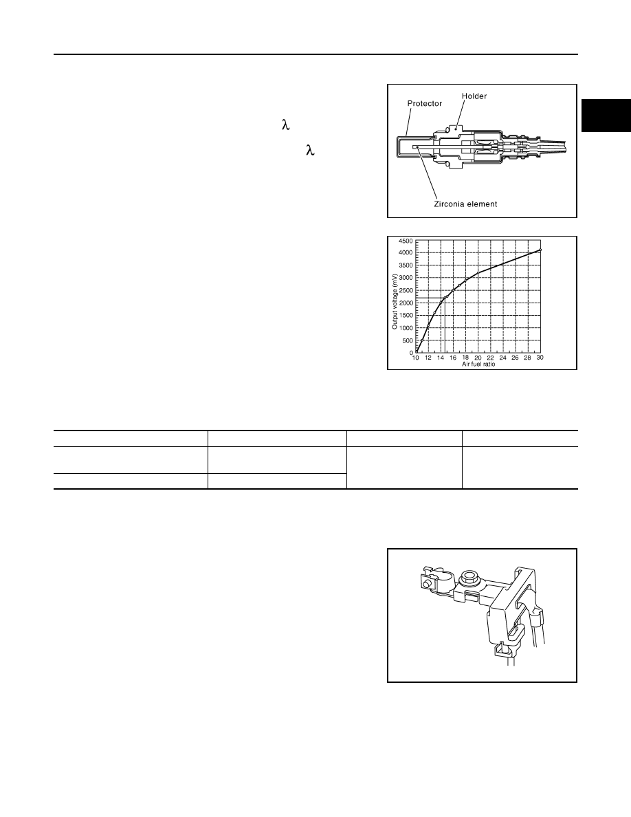
The air fuel ratio (A/F) sensor 1 is a planar one-cell limit current sen-

sor. The sensor element of the A/F sensor 1 is composed an elec-

trode layer, which transports ions. It has a heater in the element.
The sensor is capable of precise measurement   = 1, but also in the

lean and rich range. Together with its control electronics, the sensor
outputs a clear, continuous signal throughout a wide   range.

The exhaust gas components diffuse through the diffusion layer at

the sensor cell. An electrode layer is applied voltage, and this current

relative oxygen density in lean. Also this current relative hydrocar-

bon density in rich.

Therefore, the A/F sensor 1 is able to indicate air fuel ratio by this

electrode layer of current. In addition, a heater is integrated in the

sensor to ensure the required operating temperature of about 800

°C

(1,472

°F).

Air Fuel Ratio Sensor 1 Heater

INFOID:0000000009266956

SYSTEM DESCRIPTION

The ECM performs ON/OFF duty control of the A/F sensor 1 heater corresponding to the engine operating

condition to keep the temperature of A/F sensor 1 element within the specified range.

Battery Current Sensor

INFOID:0000000009496745

The battery current sensor is installed to the battery cable at the neg-

ative terminal. The sensor measures the charging/discharging cur-

rent of the battery.

The power generation voltage variable control enables fuel con-

sumption to be decreased by reducing the engine load which is

caused by the power generation of the generator.

Based on sensor signals, ECM judges whether or not the power

generation voltage variable control is performed. When performing

the power generation voltage variable control, ECM calculates the

target power generation voltage based on the sensor signal. And

ECM sends the calculated value as the power generation command

value to IPDM E/R.

CAUTION:

Never connect the electrical component or the ground wire directly to the battery terminal. The con-

nection causes the malfunction of the power generation voltage variable control, and then the battery

discharge may occur.

JMBIA0112GB

PBIB3354E

Sensor

Input Signal to ECM

ECM function

Actuator

Camshaft position sensor (PHASE)
Crankshaft position sensor (POS)

Engine speed

Air fuel ratio (A/F) sensor 1 
heater control

Air fuel ratio (A/F) sensor 1 
heater

Mass air flow sensor

Amount of intake air

JPBIA3262ZZ

EC-20

< SYSTEM DESCRIPTION >

[HR16DE]

COMPONENT PARTS

Camshaft Position Sensor

INFOID:0000000009266957

The camshaft position sensor senses the protrusion of camshaft to

identify a particular cylinder. The camshaft position sensor senses

the piston position.

When the crankshaft position sensor system becomes inoperative,

the camshaft position sensor provides various controls of engine

parts instead, utilizing timing of cylinder identification signals.

The sensor consists of a permanent magnet and Hall IC.

When engine is running, the high and low parts of the teeth cause

the gap with the sensor to change.

The changing gap causes the magnetic field near the sensor to

change.

Due to the changing magnetic field, the voltage from the sensor

changes. 

ECM receives the signals as shown in the figure.

Clutch Pedal Position Switch

INFOID:0000000009614049

When the clutch pedal is depressed, the clutch pedal position switch turns ON and the clutch pedal position

switch signal is sent to the ECM. The ECM judges the clutch pedal conditions via the signal (ON or OFF).

Cooling Fan

INFOID:0000000009266958

Cooling fan operates at low and high speed when the current flows in the cooling fan motor.

Refer to 

EC-39, "COOLING FAN CONTROL : System Description"

 for cooling fan operation.

Crankshaft Position Sensor

INFOID:0000000009266959

The crankshaft position sensor is located on the cylinder block rear

housing facing the gear teeth (cogs) of the signal plate at end of the

crankshaft. It detects the fluctuation of the engine revolution.

The sensor consists of a permanent magnet and Hall IC.

When the engine is running, the high and low parts of the teeth

cause the gap with the sensor to change.

The changing gap causes the magnetic field near the sensor to

change.

Due to the changing magnetic field, the voltage from the sensor

changes.

The ECM receives the voltage signal and detects the fluctuation of

the engine revolution.

ECM receives the signals as shown in the figure.

PBIA9209J

JPBIA4880GB

PBIA9209J

JPBIA4880GB

COMPONENT PARTS

EC-21

< SYSTEM DESCRIPTION >

[HR16DE]

C

D

E

F

G

H

I

J

K

L

M

A

EC

N

P

O

ECM

INFOID:0000000009266960

The ECM consists of a microcomputer and connectors for signal

input and output and for power supply. The ECM controls the engine.

Electric Throttle Control Actuator

INFOID:0000000009266961

Electric throttle control actuator consists of throttle control motor, throttle position sensor, etc.

The throttle control motor is operated by the ECM and it opens and closes the throttle valve.

The current opening angle of the throttle valve is detected by the throttle position sensor and it provides feed-

back to the ECM to control the throttle valve in response to driving conditions via the throttle control motor.

Engine Coolant Temperature Sensor

INFOID:0000000009266962

The engine coolant temperature sensor is used to detect the engine

coolant temperature. The sensor modifies a voltage signal from the

ECM. The modified signal returns to the ECM as the engine coolant

temperature input. The sensor uses a thermistor which is sensitive to

the change in temperature. The electrical resistance of the ther-

mistor decreases as temperature increases.

<Reference data>

*: These data are reference values and are measured between ECM terminals.

Engine Oil Pressure Sensor

INFOID:0000000009266963

The engine oil pressure (EOP) sensor is detects engine oil pressure

and transmits a voltage signal to the ECM.

PBIA9222J

SEF594K

Engine coolant temperature [

°C (°F)]

Voltage* (V)

Resistance (k

Ω)

–10 (14)

4.4

7.0 - 11.4

20 (68)

3.5

2.10 - 2.90

50 (122)

2.2

0.68 - 1.00

90 (194)

0.9

0.236 - 0.260

SEF012P

JSBIA0292ZZ

EC-22

< SYSTEM DESCRIPTION >

[HR16DE]

COMPONENT PARTS

Engine Oil Temperature Sensor

INFOID:0000000009266964

The engine oil temperature sensor is used to detect the engine oil

temperature. The sensor modifies a voltage signal from the ECM.

The modified signal returns to the ECM as the engine oil tempera-

ture input. The sensor uses a thermistor which is sensitive to the

change in temperature. The electrical resistance of the thermistor

decreases as temperature increases.

<Reference data>

*: These data are reference values and are measured between ECM terminals.

EVAP Canister Purge Volume Control Solenoid Valve

INFOID:0000000009266965

The EVAP canister purge volume control solenoid valve uses a ON/

OFF duty to control the flow rate of fuel vapor from the EVAP canis-

ter. The EVAP canister purge volume control solenoid valve is

moved by ON/OFF pulses from the ECM. The longer the ON pulse,

the greater the amount of fuel vapor that will flow through the valve.

EVAP Canister Vent Control Valve

INFOID:0000000009266966

The EVAP canister vent control valve is located on the EVAP canis-

ter and is used to seal the canister vent.

This solenoid valve responds to signals from the ECM. When the

ECM sends an ON signal, the coil in the solenoid valve is energized.

A plunger will then move to seal the canister vent. The ability to seal

the vent is necessary for the on board diagnosis of other evaporative

emission control system components.

This solenoid valve is used only for diagnosis, and usually remains

opened.

When the vent is closed, under normal purge conditions, the evapo-

rative emission control system is depressurized and allows “EVAP

Control System” diagnosis.

SEF594K

Engine oil temperature [

°C (°F)]

Voltage

*

 (V)

Resistance (k

Ω)

–10 (14)

4.4

7.0 - 11.4

20 (68)

3.5

2.10 - 2.90

50 (122)

2.2

0.68 - 1.00

90 (194)

0.9

0.236 - 0.260

110 (230)

0.6

0.143 - 0.153

SEF012P

JSBIA0651ZZ

PBIB1263E


Content   ..  253  254  255  256   ..