Nissan Versa Sedan. Instruction - part 253


  Index      Nissan     Nissan Versa Sedan (2014 year) - Service and Repair Instruction


Search            copyright infringement  


Content   ..  251  252  253  254   ..


Nissan Versa Sedan. Instruction - part 253


PRECAUTIONS

EC-11

< PRECAUTION >

[HR16DE]

C

D

E

F

G

H

I

J

K

L

M

A

EC

N

P

O

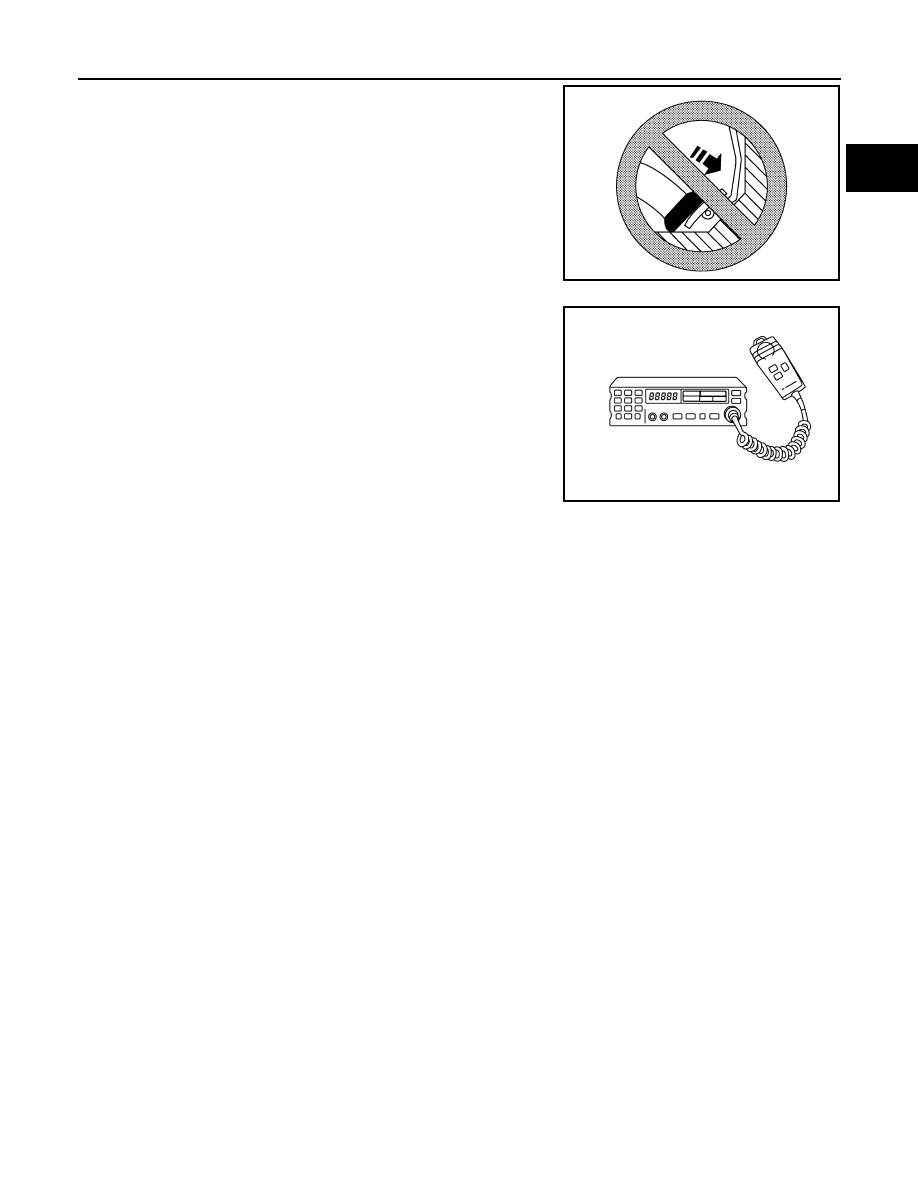
• Do not depress accelerator pedal when starting.

• Immediately after starting, do not rev up engine unnecessar-

ily.

• Do not rev up engine just prior to shutdown.

• When installing C.B. ham radio or a mobile phone, be sure to

observe the following as it may adversely affect electronic

control systems depending on installation location.

Keep the antenna as far as possible from the electronic con-

trol units.

Keep the antenna feeder line more than 20 cm (8 in) away

from the harness of electronic controls.

Do not let them run parallel for a long distance.

Adjust the antenna and feeder line so that the standing-wave

ratio can be kept smaller.

Be sure to ground the radio to vehicle body.

SEF709Y

SEF708Y

EC-12

< PREPARATION >

[HR16DE]

PREPARATION

PREPARATION

PREPARATION

Special Service Tools

INFOID:0000000009266950

NOTE:

The actual shapes of Kent-Moore tools may differ from those of special service tools illustrated here.

Commercial Service Tools

INFOID:0000000009266951

Tool number
(Kent-Moore No.)
Tool name

Description

(J-44321)
Fuel pressure gauge kit

Checks fuel pressure

(J-44321-6)
Fuel pressure adapter

Connects fuel pressure gauge to quick connector type 
fuel lines.

KV10118400
Fuel tube adapter

Measuring fuel pressure

KV10120000
Fuel tube adapter

LEC642

LBIA0376E

PBIB3043E

JSBIA0410ZZ

PREPARATION

EC-13

< PREPARATION >

[HR16DE]

C

D

E

F

G

H

I

J

K

L

M

A

EC

N

P

O

Tool name
(Kent-Moore No.)

Description

Leak detector
i.e.: (J-41416)

Locates the EVAP leak

EVAP service port adapter
i.e.: (J-41413-OBD)

Applies positive pressure through EVAP service port

Fuel filler cap adapter
i.e.: (MLR-8382)

Checks fuel tank vacuum relief valve opening pressure

Socket wrench

Removes and installs engine coolant temperature sen-
sor

Oxygen sensor thread cleaner
i.e.: (J-43897-18), (J-43897-12)

Reconditioning the exhaust system threads before in-
stalling a new oxygen sensor. Use with anti-seize lubri-
cant shown below.
a: 18 mm diameter with pitch 1.5 mm for Zirconia Ox-
ygen Sensor
b: 12 mm diameter with pitch 1.25 mm for Titania Ox-
ygen Sensor

Anti-seize lubricant
i.e.: (Permatex

TM

 133AR or 

equivalent meeting MIL specifica-
tion MIL-A-907)

Lubricating oxygen sensor thread cleaning tool when re-
conditioning exhaust system threads.

S-NT703

S-NT704

S-NT815

S-NT705

AEM488

S-NT779

EC-14

< SYSTEM DESCRIPTION >

[HR16DE]

COMPONENT PARTS

SYSTEM DESCRIPTION

COMPONENT PARTS

ENGINE CONTROL SYSTEM
ENGINE CONTROL SYSTEM : Component Parts Location

INFOID:0000000009266952

1.

Mass air flow sensor
(with intake air temperature sensor)

2.

Electric throttle control actuator
(with built in throttle position sensor 
and throttle control motor)

3.

EVAP canister purge volume control 
solenoid valve

4.

Cooling fan motor

5.

Refrigerant pressure sensor
Refer to 

HA-12, "Component Parts 

Location"

.

6.

Battery current sensor (with built in 
battery temperature sensor

*1

)

*2

7.

ECM

8.

IPDM E/R
Refer to 

PCS-5, "Component Parts 

Location"

 (WITH I-KEY) or 

PCS-32, 

"Component Parts Location"

 (WITH-

OUT I-KEY).

JSBIA3600ZZ


Content   ..  251  252  253  254   ..