Nissan Versa Sedan. Instruction - part 256


  Index      Nissan     Nissan Versa Sedan (2014 year) - Service and Repair Instruction


Search            copyright infringement  


Content   ..  254  255  256  257   ..


Nissan Versa Sedan. Instruction - part 256


COMPONENT PARTS

EC-23

< SYSTEM DESCRIPTION >

[HR16DE]

C

D

E

F

G

H

I

J

K

L

M

A

EC

N

P

O

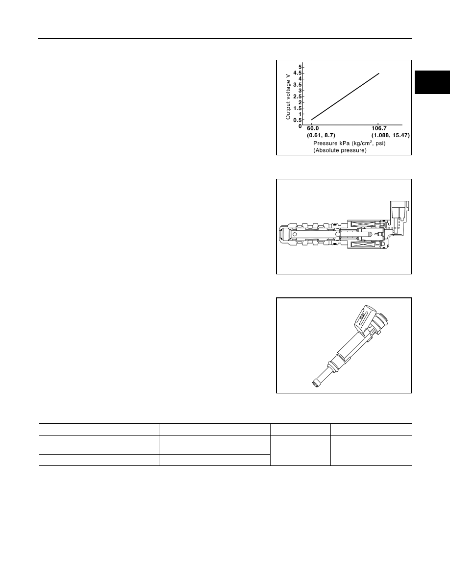
EVAP Control System Pressure Sensor

INFOID:0000000009266967

The EVAP control system pressure sensor detects pressure in the

purge line. The sensor output voltage to the ECM increases as pres-

sure increases.

Exhaust Valve Timing Control Solenoid Valve

INFOID:0000000009266968

Exhaust valve timing control solenoid valve is activated by ON/OFF

pulse duty (ratio) signals from the ECM.

The exhaust valve timing control solenoid valve changes the oil

amount and direction of flow through exhaust valve timing control

unit or stops oil flow.

The longer pulse width retards valve angle.

The shorter pulse width advances valve angle.

When ON and OFF pulse widths become equal, the solenoid valve

stops oil pressure flow to fix the exhaust valve angle at the control

position.

Fuel Injector

INFOID:0000000009266969

The fuel injector is a small, precise solenoid valve. When the ECM

supplies a ground to the fuel injector circuit, the coil in the fuel injec-

tor is energized. The energized coil pulls the ball valve back and

allows fuel to flow through the fuel injector into the intake manifold.

The amount of fuel injected depends upon the injection pulse dura-

tion. Pulse duration is the length of time the fuel injector remains

open. The ECM controls the injection pulse duration based on

engine fuel needs.

Fuel Pump

INFOID:0000000009266970

*: ECM determines the start signal status by the signals of engine speed and battery voltage.

The ECM activates the fuel pump for a few seconds after the ignition switch is turned ON to improve engine

start ability. If the ECM receives a engine speed signal from the crankshaft position sensor (POS) and cam-

shaft position sensor (PHASE), it knows that the engine is rotating, and causes the pump to operate. If the

engine speed signal is not received when the ignition switch is ON, the engine stalls. The ECM stops pump

operation and prevents battery discharging, thereby improving safety. The ECM does not directly drive the fuel

pump. It controls the ON/OFF fuel pump relay, which in turn controls the fuel pump.

PBIB3370E

JSBIA0652ZZ

JSBIA0742ZZ

Sensor

Input signal to ECM

ECM function

Actuator

Crankshaft position sensor (POS)
Camshaft position sensor (PHASE)

Engine speed*

Fuel pump control

Fuel pump relay

Fuel pump

Battery

Battery voltage*

EC-24

< SYSTEM DESCRIPTION >

[HR16DE]

COMPONENT PARTS

Heated Oxygen Sensor 2

INFOID:0000000009266971

The heated oxygen sensor 2, after three way catalyst (manifold),

monitors the oxygen level in the exhaust gas.

Even if switching characteristics of the air fuel ratio (A/F) sensor 1

are shifted, the air-fuel ratio is controlled to stoichiometric, by the sig-

nal from the heated oxygen sensor 2.

This sensor is made of ceramic zirconia. The zirconia generates volt-

age from approximately 1 V in richer conditions to 0 V in leaner con-

ditions.

Under normal conditions the heated oxygen sensor 2 is not used for

engine control operation.

Heated Oxygen Sensor 2 Heater

INFOID:0000000009266972

SYSTEM DESCRIPTION

The ECM performs ON/OFF control of the heated oxygen sensor 2 heater corresponding to the engine speed,

amount of intake air and engine coolant temperature. 

OPERATION

Ignition Coil With Power Transistor

INFOID:0000000009266973

The ignition signal from the ECM is sent to and amplified by the power transistor. The power transistor turns

ON and OFF the ignition coil primary circuit. This ON/OFF operation induces the proper high voltage in the coil

secondary circuit.

Condition

Fuel pump operation

Ignition switch is turned to ON.

Operates for 1 second.

Engine running and cranking

Operates.

When engine is stopped

Stops in 1.5 seconds.

Except as shown above

Stops.

SEF327R

Sensor

Input signal to ECM

ECM function

Actuator

Camshaft position sensor (PHASE)
Crankshaft position sensor (POS)

Engine speed

Heated oxygen sensor 2 
heater control

Heated oxygen sensor 2 heater

Engine coolant temperature sensor

Engine coolant temperature

Mass air flow sensor

Amount of intake air

Engine speed

Heated oxygen sensor 2 heater

Above 3,600 rpm

OFF

Below 3,600 rpm after the following conditions are met.
• Engine: After warming up
• Keeping the engine speed between 3,500 and 4,000 rpm for 1 minute and at idle for 1 minute 

under no load

ON

COMPONENT PARTS

EC-25

< SYSTEM DESCRIPTION >

[HR16DE]

C

D

E

F

G

H

I

J

K

L

M

A

EC

N

P

O

Intake Air Temperature Sensor

INFOID:0000000009266974

The intake air temperature sensor is built-into mass air flow sensor

(1). The sensor detects intake air temperature and transmits a signal

to the ECM.

The temperature sensing unit uses a thermistor which is sensitive to

the change in temperature. Electrical resistance of the thermistor

decreases in response to the temperature rise.

<Reference data>

*: These data are reference values and are measured between ECM terminals.

Intake Valve Timing Control Solenoid Valve

INFOID:0000000009266975

Intake valve timing control solenoid valve is activated by ON/OFF

pulse duty (ratio) signals from the ECM.

The intake valve timing control solenoid valve changes the oil

amount and direction of flow through intake valve timing control unit

or stops oil flow.

The longer pulse width advances valve angle.

The shorter pulse width retards valve angle.

When ON and OFF pulse widths become equal, the solenoid valve

stops oil pressure flow to fix the intake valve angle at the control

position.

Knock Sensor

INFOID:0000000009266976

The knock sensor is attached to the cylinder block. It senses engine

knocking using a piezoelectric element. A knocking vibration from

the cylinder block is sensed as vibrational pressure. This pressure is

converted into a voltage signal and sent to the ECM.

PBIA9559J

Intake air temperature [

°C (°F)]

Voltage* (V)

Resistance (k

Ω)

25 (77)

3.3

1.800 - 2.200

80 (176)

1.2

0.283 - 0.359

SEF012P

PBIB1842E

JSBIA0284ZZ

EC-26

< SYSTEM DESCRIPTION >

[HR16DE]

COMPONENT PARTS

Malfunction Indicator Lamp (MIL)

INFOID:0000000009266977

The MIL is located on the combination meter.

The MIL will illuminate when the ignition switch is turned ON without

the engine running. This is a bulb check.

When the engine is started, the MIL should turn OFF. If MIL remains

ON or continues blinking, the on board diagnostic system detects a

DTC(s) that affects exhaust gas.

For details, refer to 

EC-58, "DIAGNOSIS DESCRIPTION : Malfunc-

tion Indicator Lamp (MIL)"

.

Mass Air Flow Sensor

INFOID:0000000009266978

The mass air flow sensor (1) is placed in the stream of intake air. It

measures the intake flow rate by measuring a part of the entire

intake flow. The mass air flow sensor controls the temperature of the

hot wire to a certain amount. The heat generated by the hot wire is

reduced as the intake air flows around it. The more air, the greater

the heat loss. 

Therefore, the electric current supplied to hot wire is changed to

maintain the temperature of the hot wire as air flow increases. The

ECM detects the air flow by means of this current change.

Oil Pressure Warning Lamp

INFOID:0000000009266979

Oil pressure warning lamp is located on the combination meter. 

It indicates the low pressure of the engine oil and the malfunction of

the engine oil pressure system. 

Combination meter turns the oil pressure warning lamp ON/OFF

according to the oil pressure warning lamp signal received from

ECM via CAN communication.

For details, refer to 

EC-44, "ENGINE PROTECTION CONTROL AT

LOW ENGINE OIL PRESSURE : System Description"

.

Refrigerant Pressure Sensor

INFOID:0000000009266980

The refrigerant pressure sensor is installed at the condenser of the air conditioner system. The sensor uses an

electrostatic volume pressure transducer to convert refrigerant pressure to voltage. The voltage signal is sent

to ECM, and ECM controls cooling fan system.

JSBIA1315ZZ

PBIA9559J

PBIA8559J

PBIB2657E


Content   ..  254  255  256  257   ..