Nissan Versa Sedan. Instruction - part 250


  Index      Nissan     Nissan Versa Sedan (2014 year) - Service and Repair Instruction


Search            copyright infringement  


Content   ..  248  249  250  251   ..


Nissan Versa Sedan. Instruction - part 250


DLK-318

< REMOVAL AND INSTALLATION >

[WITHOUT INTELLIGENT KEY SYSTEM]

REMOTE KEYLESS ENTRY RECEIVER

REMOTE KEYLESS ENTRY RECEIVER

Removal and Installation

INFOID:0000000009269029

REMOVAL

1. Remove the glove box. Refer to 

IP-22, "Removal and Installation"

.

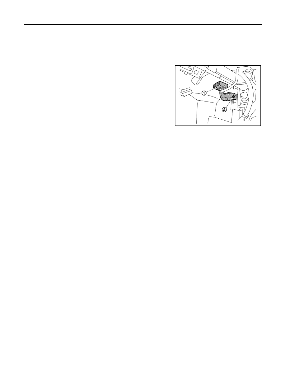
2. Remove the remote keyless entry receiver bolt (A).
3. Disconnect the harness connector from remote keyless entry

receiver and remove remote keyless entry receiver (1)

INSTALLATION

Installation is in the reverse order of removal.

JMKIA7947ZZ

KEYFOB BATTERY

DLK-319

< REMOVAL AND INSTALLATION >

[WITHOUT INTELLIGENT KEY SYSTEM]

C

D

E

F

G

H

I

J

L

M

A

B

DLK

N

O

P

KEYFOB BATTERY

Removal and Installation

INFOID:0000000009269030

REPLACEMENT

1. Remove screw from the rear of keyfob.

2. Place the key with the lower case facing up. Use a suitable tool wrapped with tape between upper case

and lower case and separate the lower case from the upper case.

CAUTION:

• Do not touch the circuit board or battery terminal. Doing so could cause the keyfob to malfunc-

tion

• The keyfob is water-resistant. However, if it does get wet, immediately wipe it dry. 

3. When replacing the circuit board assembly, remove circuit board assembly from the upper case.

[Circuit board assembly: Switch rubber + Board surface]

CAUTION:

Do not touch the printed circuits directly.

4. Remove the battery from the lower case and replace it.

CAUTION:

When replacing battery, keep dirt, grease, and other foreign materials off the electrode contact

area.

5. After replacement, fit the lower and upper cases together and tighten with the screw.

CAUTION:

After replacing the battery, Be sure to check that door locking operates normally using the keyfob.

Refer to 

DLK-255, "Component Function Check"

.

Battery replacement

: Coin-type lithium battery 
(CR1620)

EC-1

ENGINE

C

D

E

F

G

H

I

J

K

L

M

SECTION 

EC

A

EC

N

O

P

CONTENTS

ENGINE CONTROL SYSTEM

HR16DE

PRECAUTION ...............................................

8

PRECAUTIONS ...................................................

8

Precaution for Supplemental Restraint System 
(SRS) "AIR BAG" and "SEAT BELT PRE-TEN-
SIONER" .................................................................
..

8

Precaution for Procedure without Cowl Top Cover ......

8

On Board Diagnostic (OBD) System of Engine 
and A/T or CVT  .......................................................
..

8

General Precautions  .................................................

9

PREPARATION ...........................................

12

PREPARATION ..................................................

12

Special Service Tools ..............................................

12

Commercial Service Tools  ......................................

12

SYSTEM DESCRIPTION  .............................

14

COMPONENT PARTS  .......................................

14

ENGINE CONTROL SYSTEM ...................................

14

ENGINE CONTROL SYSTEM : 
Component Parts Location ....................................

14

ENGINE CONTROL SYSTEM : Component De-
scription ...................................................................

17

Accelerator Pedal Position Sensor ..........................

18

Air Fuel Ratio Sensor 1  ...........................................

19

Air Fuel Ratio Sensor 1 Heater  ...............................

19

Battery Current Sensor  ...........................................

19

Camshaft Position Sensor .......................................

20

Clutch Pedal Position Switch  ..................................

20

Cooling Fan .............................................................

20

Crankshaft Position Sensor .....................................

20

ECM ........................................................................

21

Electric Throttle Control Actuator  ............................

21

Engine Coolant Temperature Sensor ......................

21

Engine Oil Pressure Sensor ....................................

21

Engine Oil Temperature Sensor ..............................

22

EVAP Canister Purge Volume Control Solenoid 
Valve ........................................................................

22

EVAP Canister Vent Control Valve ..........................

22

EVAP Control System Pressure Sensor ..................

23

Exhaust Valve Timing Control Solenoid Valve  ........

23

Fuel Injector .............................................................

23

Fuel Pump  ...............................................................

23

Heated Oxygen Sensor 2  ........................................

24

Heated Oxygen Sensor 2 Heater  ............................

24

Ignition Coil With Power Transistor  .........................

24

Intake Air Temperature Sensor  ...............................

25

Intake Valve Timing Control Solenoid Valve  ...........

25

Knock Sensor  ..........................................................

25

Malfunction Indicator Lamp (MIL)  ............................

26

Mass Air Flow Sensor ..............................................

26

Oil Pressure Warning Lamp ....................................

26

Refrigerant Pressure Sensor  ...................................

26

Stop Lamp Switch & Brake Pedal Position Switch ....

27

Throttle Control Motor ..............................................

27

Throttle Control Motor Relay  ...................................

27

Throttle Position Sensor  ..........................................

27

ASCD Steering Switch .............................................

27

STRUCTURE AND OPERATION  .....................

28

Positive Crankcase Ventilation  ................................

28

On Board Refueling Vapor Recovery (ORVR)  ........

29

SYSTEM ............................................................

30

ENGINE CONTROL SYSTEM  ...................................

30

ENGINE CONTROL SYSTEM : System Diagram ....

30

ENGINE CONTROL SYSTEM : System Descrip-
tion ...........................................................................

31

ENGINE CONTROL SYSTEM : Fail Safe  ..............

31

MULTIPORT FUEL INJECTION SYSTEM  ................

32

MULTIPORT FUEL INJECTION SYSTEM : 
System Diagram .....................................................

33

MULTIPORT FUEL INJECTION SYSTEM : Sys-
tem Description ........................................................

33

ELECTRIC IGNITION SYSTEM .................................

36

EC-2

ELECTRIC IGNITION SYSTEM : 
System Diagram ...................................................
.

36

ELECTRIC IGNITION SYSTEM : System De-
scription .................................................................
.

36

AIR CONDITIONING CUT CONTROL ......................

37

AIR CONDITIONING CUT CONTROL : System 
Diagram .................................................................
.

38

AIR CONDITIONING CUT CONTROL : System 
Description .............................................................
.

38

CAN COMMUNICATION ...........................................

39

CAN COMMUNICATION : System Description  ......

39

COOLING FAN CONTROL .......................................

39

COOLING FAN CONTROL : System Diagram .......

39

COOLING FAN CONTROL : System Description ...

39

EVAPORATIVE EMISSION SYSTEM .......................

40

EVAPORATIVE EMISSION SYSTEM : System 
Diagram .................................................................
.

41

EVAPORATIVE EMISSION SYSTEM : System 
Description .............................................................
.

41

INTAKE VALVE TIMING CONTROL  ........................

42

INTAKE VALVE TIMING CONTROL : System Di-
agram ....................................................................
.

42

INTAKE VALVE TIMING CONTROL : System De-
scription .................................................................
.

42

EXHAUST VALVE TIMING CONTROL  ....................

43

EXHAUST VALVE TIMING CONTROL : System 
Diagram .................................................................
.

43

EXHAUST VALVE TIMING CONTROL : System 
Description .............................................................
.

43

ENGINE PROTECTION CONTROL AT LOW EN-
GINE OIL PRESSURE  .............................................
.

44

ENGINE PROTECTION CONTROL AT LOW EN-
GINE OIL PRESSURE : System Diagram .............
.

44

ENGINE PROTECTION CONTROL AT LOW EN-
GINE OIL PRESSURE : System Description  ........
.

44

FUEL FILLER CAP WARNING SYSTEM .................

45

FUEL FILLER CAP WARNING SYSTEM : 
System Diagram ...................................................
.

45

FUEL FILLER CAP WARNING SYSTEM : System 
Description .............................................................
.

45

AUTOMATIC SPEED CONTROL DEVICE (ASCD) ...

46

AUTOMATIC SPEED CONTROL DEVICE (AS-
CD) : System Diagram ...........................................
.

46

AUTOMATIC SPEED CONTROL DEVICE (AS-
CD) : System Description  ......................................
.

46

ALTERNATOR POWER GENERATION VOLT-
AGE VARIABLE CONTROL SYSTEM  ....................
.

47

ALTERNATOR POWER GENERATION VOLT-
AGE VARIABLE CONTROL SYSTEM : System 
Description .............................................................
.

47

OPERATION ......................................................

48

AUTOMATIC SPEED CONTROL DEVICE (ASCD) ...

48

AUTOMATIC SPEED CONTROL DEVICE (AS-
CD) : Switch Name and Function ............................

48

ON BOARD DIAGNOSTIC (OBD) SYSTEM .....

50

Diagnosis Description  .............................................

50

GST (Generic Scan Tool)  .......................................

50

DIAGNOSIS SYSTEM (ECM) ............................

51

DIAGNOSIS DESCRIPTION  .....................................

51

DIAGNOSIS DESCRIPTION : 1st Trip Detection 
Logic and Two Trip Detection Logic ........................

51

DIAGNOSIS DESCRIPTION : DTC and Freeze 
Frame Data  .............................................................

51

DIAGNOSIS DESCRIPTION : Counter System ......

52

DIAGNOSIS DESCRIPTION : Driving Pattern ........

55

DIAGNOSIS DESCRIPTION : System Readiness 
Test (SRT) Code .....................................................

56

DIAGNOSIS DESCRIPTION : Permanent Diag-
nostic Trouble Code (Permanent DTC)  ..................

57

DIAGNOSIS DESCRIPTION : Malfunction Indica-
tor Lamp (MIL)  ........................................................

58

On Board Diagnosis Function  .................................

58

CONSULT Function  ................................................

61

ECU DIAGNOSIS INFORMATION .............

70

ECM ...................................................................

70

Reference Value  .....................................................

70

Fail Safe .................................................................

82

DTC Inspection Priority Chart ...............................

84

DTC Index ..............................................................

85

Test Value and Test Limit  .......................................

88

WIRING DIAGRAM  ....................................

96

ENGINE CONTROL SYSTEM ...........................

96

Wiring Diagram  .......................................................

96

BASIC INSPECTION .................................

117

DIAGNOSIS AND REPAIR WORKFLOW ........

117

Work Flow  .............................................................

117

Diagnostic Work Sheet  .........................................

120

ADDITIONAL SERVICE WHEN REPLACING 
ECM ..................................................................

122

Description ............................................................

122

Work Procedure  ....................................................

122

ACCELERATOR PEDAL RELEASED POSI-
TION LEARNING ..............................................

124

Description ............................................................

124

Work Procedure  ....................................................

124

THROTTLE VALVE CLOSED POSITION 
LEARNING .......................................................

125

Description ............................................................

125

Work Procedure  ....................................................

125

IDLE AIR VOLUME LEARNING .......................

126


Content   ..  248  249  250  251   ..