Nissan Versa Sedan. Instruction - part 192
DLK-86
< DTC/CIRCUIT DIAGNOSIS >
[WITH INTELLIGENT KEY SYSTEM]
DOOR LOCK AND UNLOCK SWITCH
Is the inspection result normal?
YES
>> Replace BCM. Refer to
BCS-69, "Removal and Installation"
NO
>> Repair or replace harness.
3.
CHECK DOOR LOCK AND UNLOCK SWITCH GROUND
Check continuity between main power window and door lock/unlock switch harness connector and ground.
Is the inspection result normal?
YES
>> GO TO 4.
NO
>> Repair or replace harness.
4.
CHECK DOOR LOCK AND UNLOCK SWITCH
DLK-86, "Component Inspection"
Is the inspection result normal?
YES
>> GO TO 5.
NO
>> Replace main power window and door lock/unlock switch. Refer to
.
5.
CHECK INTERMITTENT INCIDENT
GI-45, "Intermittent Incident"
>> Inspection End.
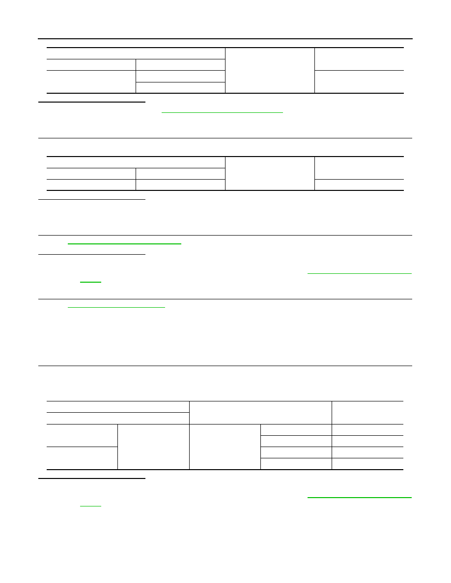
Component Inspection
INFOID:0000000009268766
1.
CHECK MAIN POWER WINDOW AND DOOR LOCK/UNLOCK SWITCH
1. Turn ignition switch OFF.
2. Disconnect main power window and door lock/unlock switch connector.
3. Check continuity between main power window and door lock/unlock switch terminals.
Is the inspection result normal?
YES
>> Inspection End
NO
>> Replace main power window and door lock/unlock switch. Refer to
.
BCM
Ground
Continuity
Connector
Terminal
M97
12
No
13
Main power window and door lock/unlock switch
Ground
Continuity
Connector
Terminal
D8
17
Yes
Main power window and door lock/unlock switch
Condition
Continuity
Terminal
6
17
main power window
and door lock/ unlock
switch
LOCK
No
UNLOCK
Yes
18
LOCK
Yes
UNLOCK
No