Nissan Versa Sedan. Instruction - part 190


  Index      Nissan     Nissan Versa Sedan (2014 year) - Service and Repair Instruction


Search            copyright infringement  


Content   ..  188  189  190  191   ..


Nissan Versa Sedan. Instruction - part 190


DLK-78

< DTC/CIRCUIT DIAGNOSIS >

[WITH INTELLIGENT KEY SYSTEM]

POWER SUPPLY AND GROUND CIRCUIT

POWER SUPPLY AND GROUND CIRCUIT

Diagnosis Procedure

INFOID:0000000009268753

Regarding Wiring Diagram information, refer to 

BCS-50, "Wiring Diagram"

.

1.

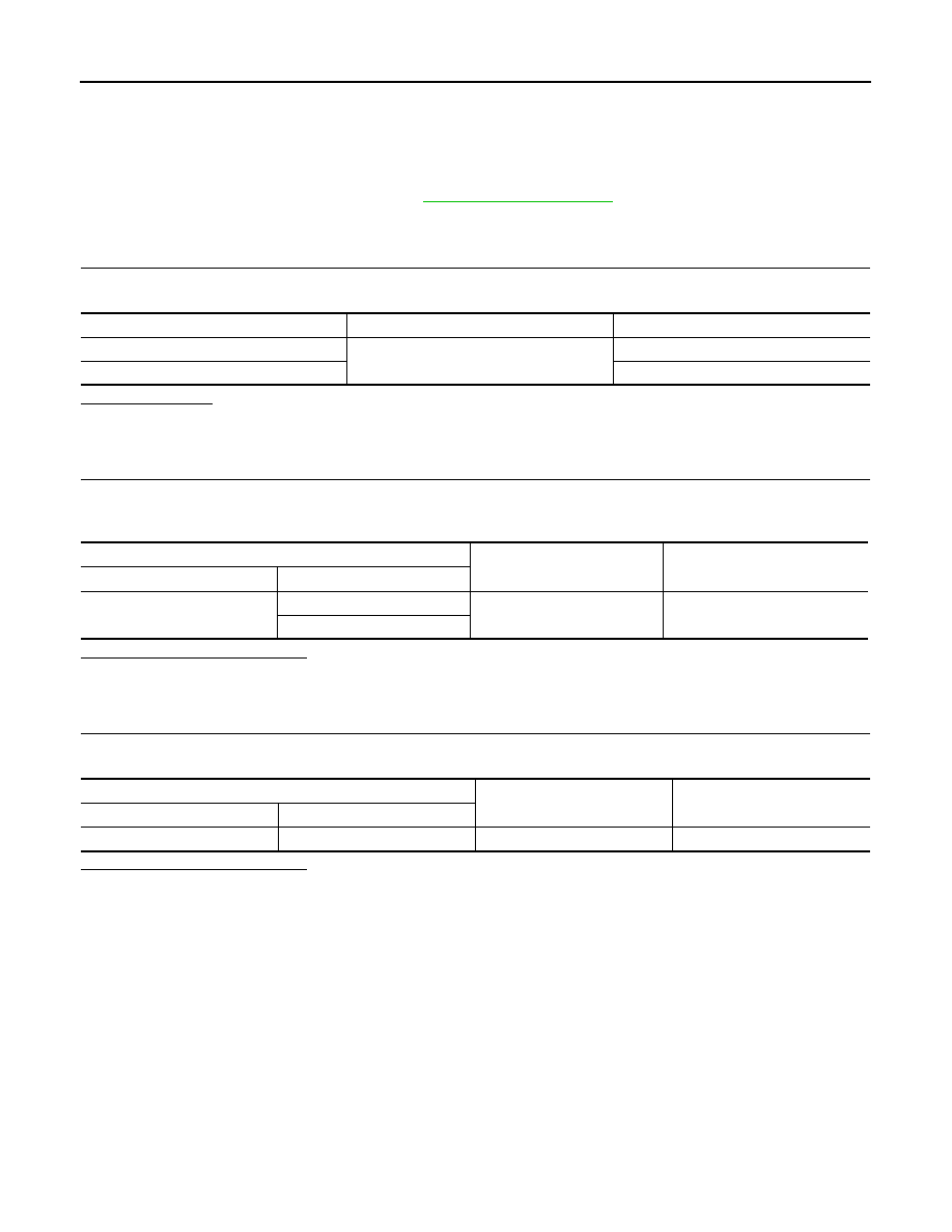
CHECK FUSES AND FUSIBLE LINK

Check that the following fuses and fusible link are not blown.

Is the fuse blown?

YES

>> Replace the blown fuse or fusible link after repairing the affected circuit.

NO

>> GO TO 2.

2.

CHECK POWER SUPPLY CIRCUIT

1. Disconnect BCM connector M99.

2. Check voltage between BCM connector M99 and ground.

Is the inspection result normal?

YES

>> GO TO 3.

NO

>> Repair harness or connector.

3.

CHECK GROUND CIRCUIT

Check continuity between BCM connector M99 and ground.

Is the inspection result normal?

YES

>> Inspection End.

NO

>> Repair harness or connector.

Terminal No.

Signal name

Fuses and fusible link No.

57

Battery power supply

12 (10A)

70

G (40A)

BCM

Ground

Voltage

Connector

Terminal

M99

57

Battery voltage

70

BCM

Ground

Continuity

Connector

Terminal

M99

67

Yes

COMBINATION METER BUZZER

DLK-79

< DTC/CIRCUIT DIAGNOSIS >

[WITH INTELLIGENT KEY SYSTEM]

C

D

E

F

G

H

I

J

L

M

A

B

DLK

N

O

P

COMBINATION METER BUZZER

Component Function Check

INFOID:0000000009268754

1.

CHECK FUNCTION

1. Select INTELLIGENT KEY of BCM using CONSULT.

2. Select INSIDE BUZZER in ACTIVE TEST mode.

3. Touch Key, Knob or Take Out to check that it works normally.
Is the inspection result normal?

Yes

>> Combination meter buzzer is OK.

No

>> Refer to 

DLK-79, "Diagnosis Procedure"

.

Diagnosis Procedure

INFOID:0000000009268755

1.

CHECK METER BUZZER CIRCUIT

Refer to 

WCS-35, "Component Function Check"

.

Is the inspection result normal?

Yes

>> GO TO 2.

No

>> Repair or replace harness.

2.

CHECK INTERMITTENT INCIDENT

Refer to 

GI-45, "Intermittent Incident"

.

>> Inspection End.

DLK-80

< DTC/CIRCUIT DIAGNOSIS >

[WITH INTELLIGENT KEY SYSTEM]

DOOR LOCK ACTUATOR

DOOR LOCK ACTUATOR

DRIVER SIDE
DRIVER SIDE : Component Function Check

INFOID:0000000009268756

1.

CHECK FUNCTION

1. Select DOOR LOCK of BCM using CONSULT.

2. Select DOOR LOCK in ACTIVE TEST mode.

3. Touch ALL LOCK or ALL UNLK to check that it works normally.
Is the inspection result normal?

YES

>> Door lock actuator is OK.

NO

>> Refer to 

DLK-80, "DRIVER SIDE : Diagnosis Procedure"

.

DRIVER SIDE : Diagnosis Procedure

INFOID:0000000009268757

Regarding Wiring Diagram information, refer to 

DLK-50, "POWER DOOR LOCK SYSTEM : Wiring Diagram"

.

1.

CHECK DOOR LOCK ACTUATOR INPUT SIGNAL

1. Turn ignition switch OFF.

2. Disconnect front door lock actuator LH connector.

3. Check voltage between front door lock actuator LH harness connector and ground.

Is the inspection result normal?

YES

>> Replace front door lock actuator LH .

NO

>> GO TO 2.

2.

CHECK DOOR LOCK ACTUATOR CIRCUIT

1. Disconnect BCM connector and all door lock actuator connectors.

2. Check continuity between BCM harness connector and front door lock actuator LH  harness connector. 

3. Check continuity between BCM harness connector and ground.

Is the inspection result normal?

YES

>> GO TO 3.

NO

>> Repair or replace harness.

3.

CHECK BCM OUTPUT SIGNAL

1. Connect BCM connector.

2. Check voltage between front door lock actuator LH  harness connector and ground.

(+)

(–)

Condition

Voltage

(Approx.)

Front door lock actuator 

LH

Connector

Terminal

D14

1

Ground

Door lock and unlock switch

Lock

12 V

2

Unlock

BCM

Front door lock actuator LH 

Continuity 

Connector

Terminal

Connector

Terminal

M99

65

D14

1

Yes

66

2

BCM

Ground

Continuity 

Connector

Terminal

M99

65

No

66

DOOR LOCK ACTUATOR

DLK-81

< DTC/CIRCUIT DIAGNOSIS >

[WITH INTELLIGENT KEY SYSTEM]

C

D

E

F

G

H

I

J

L

M

A

B

DLK

N

O

P

Is the inspection result normal?

YES

>> Check for internal short of each door lock actuator.

NO

>> Replace BCM. Refer to 

BCS-69, "Removal and Installation"

.

PASSENGER SIDE
PASSENGER SIDE : Component Function Check

INFOID:0000000009268758

1.

CHECK FUNCTION

1. Select DOOR LOCK of BCM using CONSULT.

2. Select DOOR LOCK in ACTIVE TEST mode.

3. Touch ALL LOCK or ALL UNLK to check that it works normally.
Is the inspection result normal?

YES

>> Door lock actuator is OK.

NO

>> Refer to 

DLK-81, "PASSENGER SIDE : Diagnosis Procedure"

.

PASSENGER SIDE : Diagnosis Procedure

INFOID:0000000009268759

Regarding Wiring Diagram information, refer to 

DLK-50, "POWER DOOR LOCK SYSTEM : Wiring Diagram"

.

1.

CHECK DOOR LOCK ACTUATOR INPUT SIGNAL

1. Turn ignition switch OFF.

2. Disconnect front door lock actuator RH connector.

3. Check voltage between front door lock actuator RH harness connector and ground.

Is the inspection result normal?

YES

>> Replace front door lock actuator (RH).

NO

>> GO TO 2.

2.

CHECK DOOR LOCK ACTUATOR CIRCUIT

1. Disconnect BCM connector and all door lock actuators. 

2. Check continuity between BCM harness connector and front door lock actuator RH harness connector. 

3. Check continuity between BCM harness connector and ground.

(+)

(–)

Condition

Voltage

(Approx.)

BCM

Connector

Terminal

M99

65

Ground

Door lock and unlock switch

Lock

12 V

66

Unlock

(+)

(–)

Condition

Voltage

(Approx.)

Front door lock actuator

RH

Connector

Terminal

D114

5

Ground

Door lock and unlock switch

Lock

12 V

6

Unlock

BCM

Front door lock actuator RH

Continuity 

Connector

Terminal

Connector

Terminal

M99

65

D114

5

Yes

59

6


Content   ..  188  189  190  191   ..