Nissan Murano Hybrid (2016 year). Manual - part 13


  Index      Nissan     Nissan Murano Hybrid - service manual 2016 year in english


Search            copyright infringement  


Content   ..  11  12  13  14   ..


Nissan Murano Hybrid (2016 year). Manual - part 13


To remove the fuel-filler cap:

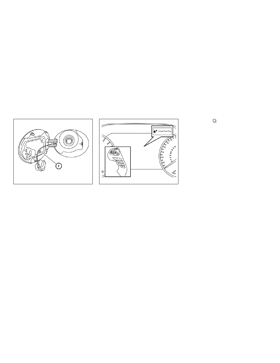
1. Turn the fuel-filler cap counterclockwise to

remove.

2. Put the fuel-filler cap on the cap holder

1

while refueling.

To install the fuel-filler cap:

1. Insert the fuel-filler cap straight into the fuel-

filler tube.

2. Turn the fuel-filler cap clockwise until a

single click is heard.

LOOSE FUEL CAP warning

The LOOSE FUEL CAP warning message ap-
pears in the vehicle information display when the
fuel-filler cap is not tightened correctly after the
vehicle has been refueled. It may take a few
driving trips for the message to be displayed. To
turn off the warning message, perform the follow-
ing:

1. Remove and install the fuel-filler cap as soon

as possible. For additional information, refer
to “Fuel-filler cap” in this section.

2. Tighten the fuel-filler cap until it clicks.

3. Press the

button on the steering

wheel for about one second to turn off the
LOOSE FUEL CAP warning message after
tightening the fuel-filler cap.

LPD2288

LPD2298

3-28

Pre-driving checks and adjustments

WARNING

● Do not adjust the steering wheel while

driving. You could lose control of your
vehicle and cause an accident.

● Do not adjust the steering wheel any

closer to you than is necessary for
proper steering operation and comfort.
The driver’s air bag inflates with great
force. If you are unrestrained, leaning
forward, sitting sideways or out of posi-
tion in any way, you are at greater risk of
injury or death in a crash. You may also
receive serious or fatal injuries from the
air bag if you are up against it when it
inflates. Always sit back against the
seatback and as far away as practical
from the steering wheel. Always use the
seat belts.

MANUAL OPERATION (if so
equipped)

Tilt and telescopic operation

Pull the lock lever

1

down:

● Adjust the steering wheel up or down in

direction

2

to the desired position.

● Adjust the steering wheel forward or back-

ward in direction

3

to the desired position.

Push the lock lever

1

up firmly to lock the

steering wheel in place.

AUTOMATIC OPERATION (if so
equipped)

Tilt and telescopic operation

To adjust the steering wheel move the switch

1

in the following directions:

● Adjust the steering wheel up or down in

direction

2

to the desired tilt position.

● Adjust the steering wheel forward or back-

ward in direction

3

to the desired tele-

scopic position.

LPD2339

LPD2410

STEERING WHEEL

Pre-driving checks and adjustments

3-29

CAUTION

For vehicles with automatic drive posi-
tioner: Failure to reset the tilt and tele-
scoping functions of the steering wheel,
after the vehicle’s battery has been dis-
charged, may prevent the steering wheel
position from being adjusted.

For vehicles with automatic drive positioner: Both
the tilt and telescopic steering operation must be
reset after the vehicle’s battery has been dis-
charged in order to prevent the tilt and telescopic
operation from locking in one position. When the
battery has been recharged or replaced, perform
the following:

● For tilt operation: Adjust the switch

1

so

the steering wheel moves to the highest
position

2

that can be reached.

● For telescopic operation: Adjust the switch

1

so the steering wheel moves to the most

forward and backward position

3

that can

be reached.

Performing these operations resets the range of
the steering wheel’s tilt and telescopic function.

Entry/Exit function

The automatic drive positioner system will make
the steering wheel move up automatically when
the driver’s door is opened and the ignition
switch is in the LOCK position. This lets the driver
get into and out of the seat more easily. The
steering wheel moves back into position when
the driver’s door is closed and the ignition switch
is pushed.

For additional information, refer to “Automatic
drive positioner” in this section.

WPD0344

SUN VISORS

3-30

Pre-driving checks and adjustments

1

To block glare from the front, swing down the
main sun visor.

2

To block glare from the side, remove the
main sun visor from the center mount and
swing the visor to the side.

3

To extend the sun visor, slide in or out as
needed.

CAUTION

● Do not store the sun visor before return-

ing

the

extension

to

its

original

position.

● Do not pull the extension sun visor

forcedly downward.

VANITY MIRRORS

To access the vanity mirror, pull the sun visor
down and flip open the mirror cover. The vanity
mirror will illuminate when the mirror cover is
open.

CARD HOLDER

Do not view information while operating the ve-
hicle.

LPD2289

LPD2340

Pre-driving checks and adjustments

3-31

AUTOMATIC ANTI-GLARE
REARVIEW MIRROR

The inside mirror is designed so that it automati-
cally dims during night time conditions and ac-
cording to the intensity of the headlights of the
vehicle following you. The automatic anti-glare
feature is activated when the ignition switch is in
the ON position.

NOTE:

Do not hang any objects over the sensors

1

or apply glass cleaner to the sensors.

Doing so will reduce the sensitivity of the
sensors, resulting in improper operation.

The indicator light

2

will illuminate when the

automatic anti-glare feature is operating.

● To turn off the anti-glare feature, press

the O button. The indicator light will turn
off.

● To turn on the anti-glare feature, press

the | button again. The indicator light will
turn on.

For information on HomeLink® Universal Trans-
ceiver operation, refer to the “HomeLink® Uni-
versal Transceiver” in the “Instruments and con-
trols” section of this manual.

OUTSIDE MIRRORS

WARNING

● Do not adjust the mirrors while driving.

You could lose control of your vehicle
and cause an accident.

● Objects viewed in the outside mirror on

the passenger side are closer than they
appear. Be careful when moving to the
right. Using only this mirror could cause
an accident. Use the inside mirror or
glance over your shoulder to properly
judge distances to other objects.

LPD0469

MIRRORS

3-32

Pre-driving checks and adjustments

Electric control type

The outside mirror remote control will operate
only when the ignition switch is in the ACC or ON
position.

Move the small switch

1

to select the left or right

mirror. Adjust each mirror to the desired position
using the large switch

2

.

Manual folding outside mirrors

Pull the outside mirror toward the door to fold it.

Reverse tilt-down feature

The reverse tilt-down feature will turn both out-
side mirror surfaces downward to provide better
rear visibility close to the vehicle when the mirror
control switch is in either the L or R position.

The mirrors automatically returns to their original
position when you shift out of R (Reverse).

The outside mirror surfaces will return to their
original position when one of the following has
occurred:

● The shift lever is moved to any position other

than R (Reverse).

● The outside mirror control switch is set to the

neutral or center position.

● The ignition switch is placed in the OFF

position.

NOTE:

If the outside mirror control switch is in the
Center position, mirror surface will NOT
turn downward when the shift lever is
moved to R (Reverse).

For additional information regarding this feature,
refer to “Automatic drive positioner” in this sec-
tion.

Heated mirrors

The electric control type outside mirrors can be
heated to defrost, defog, or de-ice for improved
visibility. For additional information, refer to “Rear
window defroster switch” in the Instruments and
controls” section of this manual.

LPD2083

LPD2112

Pre-driving checks and adjustments

3-33

The automatic drive positioner system has three
features:

● Memory storage function (Key-link)
● Memory storage function (Switch)
● Entry/exit function

Key-link, when enabled, automatically retains the
driver’s last seat, automatic steering wheel (if so
equipped), and outside mirror positions for that
specific key when the ignition is turned from ON
to OFF.

Each memory switch button (1 or 2) on the driv-
er’s door can also store one additional position
which is independent of the key-linked position.

MEMORY STORAGE FUNCTION
(Key-Link)

Use the following process to setup key-link:

1. Unlock the vehicle with the desired Intelli-

gent Key while the ignition is OFF.

2. Place the ignition in the ON position.

3. Within the “Settings” menu of the vehicle

information display, select “Key-Linked Set-
tings” and press the OK button on the steer-
ing switch.

4. While in the menu, press the OK button on

the steering switch to turn the system
ON/OFF.

Once step 4 is completed, every time the ignition
is switched from ON to OFF, the memory posi-
tions of the driver’s seat, automatic steering
wheel (if so equipped) and the outside mirrors
are linked to the Intelligent Key.

Follow the same procedure if you want to
link the 2nd, 3rd or 4th Intelligent Key.

NOTE:

If new memory positions are set prior to
turning the ignition from ON to OFF, the
previously linked memory positions for the
respective key will be overwritten by new
positions.

Recalling Intelligent Key Memory
Positions

If the “Key-Linked Settings” are enabled in the
vehicle information display for that particular key,
every time you enter the vehicle the driver’s seat,
automatic steering wheel (if so equipped), and
outside mirrors will automatically move to the
driver’s last position of the respective Intelligent
Key.

NOTE:

The key-linked memory positions can be
different from the positions stored in the
memory switch (1 or 2).

LPD2432

AUTOMATIC DRIVE POSITIONER

3-34

Pre-driving checks and adjustments

MEMORY STORAGE FUNCTION
(Switch)

Use the following process to manually store the
two memory positions in the switch:

1. Place the ignition in the ON or ACC position

(the vehicle should be stopped while setting
the memory).

2. Adjust the driver’s seat, automatic steering

wheel (if so equipped), and outside mirrors
to the desired positions by manually operat-
ing each adjusting switch. For additional in-
formation, refer to “Seats” in the “Safety—
Seats, seat belts and supplemental restraint
system” section of this manual and “Steering
wheel” and “Outside mirrors” in this section.

3. Push the SET switch and, within 5 seconds,

push the memory switch (1 or 2).

The indicator light for the pushed memory switch
will come on and stay on for approximately 5 sec-
onds. The chime will sound if the memory has
been stored.

NOTE:

If a new memory position is stored in the
same memory switch, the previous memory
position will be overwritten by the new
stored position.

Recalling Switch Memory Positions

To recall the manually stored positions, press the
memory switch (1 or 2). The driver’s seat, outside
mirrors and automatic steering wheel (if so
equipped) will move to the positions stored to
those buttons.

ENTRY/EXIT FUNCTION

This system is designed so that the driver’s seat
and automatic operation steering column will au-
tomatically move when the shift lever is in the P
(Park) position. This allows the driver to get into
and out of the driver’s seat more easily.

LPD2291

Pre-driving checks and adjustments

3-35

The driver’s seat will slide backward and the
steering wheel will move up:

● When the driver’s door is opened and the

ignition switch is in the OFF position.

● When the ignition switch is turned from

ACC to OFF with the driver’s door open.

The driver’s seat and steering wheel will return to
the previous position:

● When the ignition switch is turned to ACC or

ON while the shift lever is in the P (Park)
position.

The entry/exit function can be adjusted or can-
celed through the Vehicle Settings in the vehicle
information display by performing the following:

● Switch the Exit Seat Slide from ON to OFF.
● Switch the Exit Steering Up from ON to OFF.

Restarting the entry/exit function

If the battery cable is disconnected or if the fuse
opens, the stored memory positions may be lost
and some of the functions will be restricted.

1. Drive the vehicle over 25 mph (40 km/h).

OR

2. Open and close the driver’s door more than

two times with the ignition switch in the OFF
position.

The entry/exit function should now work properly.

SYSTEM OPERATION

The automatic drive positioner system will not
work or will stop operating under the following
conditions:

● When the vehicle speed is above 0 mph

(0 km/h).

● When any of the memory switches are

pushed while the automatic drive positioner
is operating.

● When the adjusting switch for the driver’s

seat and steering column is turned on while
the automatic drive positioner is operating.

● When the seat has already been moved to

the memorized position.

● When no seat position is stored in the

memory switch.

● When the shift lever is moved from P (Park)

to any other position.

3-36

Pre-driving checks and adjustments

4 Monitor, climate, audio, phone and voice
recognition systems

Around View® Monitor . . . . . . . . . . . . . . . . . . . . . . . . . . . . . 4-2

Around View® Monitor system operation . . . . . . . . . . 4-4
Difference between predicted and actual
distances . . . . . . . . . . . . . . . . . . . . . . . . . . . . . . . . . . . . . . 4-7
How to park with predicted course lines. . . . . . . . . . . 4-8
How to switch the display . . . . . . . . . . . . . . . . . . . . . . . 4-9
Adjusting the screen . . . . . . . . . . . . . . . . . . . . . . . . . . . 4-10
Around View® Monitor system limitations . . . . . . . . 4-11
System maintenance . . . . . . . . . . . . . . . . . . . . . . . . . . . 4-13

Moving Object Detection (MOD) . . . . . . . . . . . . . . . . . . . 4-14

MOD system operation. . . . . . . . . . . . . . . . . . . . . . . . . 4-15
Turning MOD on and off. . . . . . . . . . . . . . . . . . . . . . . . 4-16
MOD system limitations . . . . . . . . . . . . . . . . . . . . . . . . 4-16

System maintenance . . . . . . . . . . . . . . . . . . . . . . . . . . . 4-17

Vents . . . . . . . . . . . . . . . . . . . . . . . . . . . . . . . . . . . . . . . . . . . 4-18
Heater and Air Conditioner (automatic). . . . . . . . . . . . . . 4-19

Automatic operation . . . . . . . . . . . . . . . . . . . . . . . . . . . 4-20
Manual operation . . . . . . . . . . . . . . . . . . . . . . . . . . . . . . 4-21
Operating tips. . . . . . . . . . . . . . . . . . . . . . . . . . . . . . . . . 4-21

Servicing air conditioner. . . . . . . . . . . . . . . . . . . . . . . . . . . 4-22
Audio System . . . . . . . . . . . . . . . . . . . . . . . . . . . . . . . . . . . . 4-22

Antenna . . . . . . . . . . . . . . . . . . . . . . . . . . . . . . . . . . . . . . 4-22

NissanConnect

SM

Mobile Apps . . . . . . . . . . . . . . . . . . . . 4-23

Car phone or CB radio . . . . . . . . . . . . . . . . . . . . . . . . . . . . 4-23
Bluetooth® Hands-Free Phone System . . . . . . . . . . . . . 4-24
NISSAN Voice Recognition System. . . . . . . . . . . . . . . . . 4-24

1. CAMERA button

LHA3829

AROUND VIEW® MONITOR

4-2

Monitor, climate, audio, phone and voice recognition systems

WARNING

● Failure to follow the warnings and in-

structions for the proper use of the
Around View® Monitor could result in
serious injury or death.

● The Around View® Monitor is a conve-

nience feature and is not a substitute
for proper vehicle operation because it
has areas where objects cannot be
viewed. The four corners of the vehicle
in particular, are areas where objects do
not always appear in the bird’s-eye,
front, or rear views. Always check your
surroundings to be sure that it is safe to
move before operating the vehicle. Al-
ways operate the vehicle slowly.

● The driver is always responsible for

safety

during

parking

and

other

maneuvers.

● Do not use the Around View® Monitor

with the outside mirrors in the stored
position, and make sure that the liftgate
is securely closed when operating the
vehicle

using

the

Around

View®

Monitor.

● The apparent distance between objects

viewed on the Around View® Monitor
differs from the actual distance.

● The cameras are installed on the front

grille, the outside mirrors and above the
rear license plate. Do not put anything
on the vehicle that covers the cameras.

● When washing the vehicle with high-

pressure water, be sure not to spray it
around the cameras. Otherwise, water
may enter the camera unit causing wa-
ter condensation on the lens, a mal-
function, fire or an electric shock.

● Do not strike the cameras. They are

precision instruments. Doing so could
cause a malfunction or cause damage
resulting in a fire or an electric shock.

CAUTION

Do not scratch the camera lens when
cleaning dirt or snow from the front of the
camera.

The Around View® Monitor system is designed
as an aid to the driver in situations such as slot
parking or parallel parking.

The monitor displays various views of the position
of the vehicle in a split screen format.

Available views:

● Front View

An approximately 150–degree view of the
front of the vehicle.

● Rear View

An approximately 150–degree view of the
rear of the vehicle.

● Bird’s-Eye View

The surrounding views of the vehicle from
above.

● Front-Side View

The view around and ahead of the front
passenger’s side wheel.

Monitor, climate, audio, phone and voice recognition systems

4-3

To display the multiple views, the Around View®
Monitor system uses cameras located in the front
grille, on the vehicle’s outside mirrors and one
just above the vehicle’s license plate

1

.

AROUND VIEW® MONITOR
SYSTEM OPERATION

With the ignition switch in the ON position, move
the shift lever to the R (Reverse) position or press
the CAMERA button to operate the Around
View® Monitor.

The screen displayed on the Around View®
Monitor will automatically return to the previous
screen 3 minutes after the CAMERA button has

been pressed with the shift lever in a position
other than the R (Reverse) position.

Available views

WARNING

● The distance guide lines and the vehicle

width lines should be used as a refer-
ence only when the vehicle is on a
paved, level surface. The apparent dis-
tance viewed on the monitor may be
different than the actual distance be-
tween

the

vehicle

and

displayed

objects.

● Use the displayed lines and the bird’s-

eye view as a reference. The lines and
the bird’s-eye view are greatly affected
by the number of occupants, cargo, fuel
level, vehicle position, road condition
and road grade.

● If the tires are replaced with different

sized tires, the predicted course lines
and the bird’s-eye view may be dis-
played incorrectly.

● When driving the vehicle up a hill, ob-

jects viewed in the monitor are further
than they appear. When driving the ve-
hicle down a hill, objects viewed in the
monitor are closer than they appear.

● Objects in the rear view will appear vi-

sually opposite compared to when
viewed in the monitor and outside
mirrors.

● Use the mirrors or actually look to prop-

erly judge distances to other objects.

● On a snow-covered or slippery road,

there may be a difference between the
predicted course lines and the actual
course line.

● The vehicle width and predicted course

lines are wider than the actual width
and course.

● The displayed lines will appear slightly

off to the right, because the rearview
camera is not installed in the rear center
of the vehicle.

LHA3830

4-4

Monitor, climate, audio, phone and voice recognition systems

Front and rear view

Guiding lines that indicate the approximate ve-
hicle width and distance to objects with refer-
ence to the vehicle body line

A

are displayed on

the monitor.

Distance guide lines

Indicate distances from the vehicle body:

● Red line

1

: approximately 1.5 ft (0.5 m)

● Yellow line

2

: approximately 3 ft (1 m)

● Green line

3

: approximately 7 ft (2 m)

● Green line

4

: approximately 10 ft (3 m)

Vehicle width guide lines

5

:

Indicate the approximate vehicle width when
backing up.

Predicted course lines

6

:

Indicate the predicted course when operating the
vehicle. The predicted course lines will be dis-
played on the monitor when the steering wheel is
turned. The predicted course lines will move de-
pending on how much the steering wheel is
turned and will not be displayed while the steer-
ing wheel is in the straight-ahead position.

The front view will not be displayed when the
vehicle speed is above 6 mph (10 km/h).

NOTE:

When the monitor displays the front view
and the steering wheel turns about 90 de-
grees or less from the straight-ahead posi-
tion, both the right and left predicted
course lines

6

are displayed. When the

steering wheel turns about 90 degrees or
more, a line is displayed only on the oppo-
site side of the turn.

Front view

SAA1840

Rear view

SAA1896

Monitor, climate, audio, phone and voice recognition systems

4-5

Bird’s-eye view

The bird’s-eye view shows the overhead view of
the vehicle, which helps confirm the vehicle po-
sition and the predicted course to a parking
space.

The vehicle icon

1

shows the position of the

vehicle. Note that the apparent distance between
objects viewed in the bird’s-eye view may differ
somewhat from the actual distance to the vehicle.

The areas that the cameras cannot cover

2

are

indicated in black.

The non-viewable area

2

is highlighted in yellow

for several seconds after the bird’s-eye view is
displayed. It will be shown only the first time after
the ignition switch is placed in the ON position.

The driver can check the approximate direction
and angle of the tire on the display by the tire icon

3

when driving the vehicle forward or backward.

WARNING

● Objects in the bird’s-eye view will ap-

pear further than the actual distance.

● Tall objects, such as a curb or vehicle,

may be misaligned or not displayed at
the seam of the views.

● Objects that are above the camera can-

not be displayed.

● The view of the bird’s-eye view may be

misaligned when the camera position
alters.

● A line on the ground may be misaligned

and is not seen as being straight at the
seam of the views. The misalignment
will increase as the line proceeds away
from the vehicle.

● Tire angle display does not indicate the

actual tire angle.

Front-side view

Guiding lines

Guiding lines that indicate the approximate width
and the front end of the vehicle are displayed on
the monitor.

The front-of-vehicle line

1

shows the front part

of the vehicle.

The side-of-vehicle line

2

shows the approxi-

mate vehicle width including the outside mirrors.

The extensions

3

of both the front

1

and side

2

lines are shown with a green dotted line.

LHA3730

LHA2652

4-6

Monitor, climate, audio, phone and voice recognition systems

DIFFERENCE BETWEEN
PREDICTED AND ACTUAL
DISTANCES

The displayed guidelines and their locations on
the ground are for approximate reference only.
Objects on uphill or downhill surfaces or project-
ing objects will be actually located at distances
different from those displayed in the monitor rela-
tive to the guidelines (refer to illustrations). When
in doubt, turn around and view the objects as you
are backing up, or park and exit the vehicle to
view the positioning of objects behind the ve-
hicle.

Backing up on a steep uphill

When backing up the vehicle up a hill, the dis-
tance guide lines and the vehicle width guide
lines are shown closer than the actual distance.
Note that any object on the hill is further than it
appears on the monitor.

Backing up on a steep downhill

When backing up the vehicle down a hill, the
distance guide lines and the vehicle width guide
lines are shown farther than the actual distance.
Note that any object on the hill is closer than it
appears on the monitor.

LHA3523

LHA3524

Monitor, climate, audio, phone and voice recognition systems

4-7


Content   ..  11  12  13  14   ..