Nissan Leaf (2019 year). Manual - part 14


  Index      Nissan     Nissan Leaf - service manual 2019 year in english


Search            copyright infringement  


Content   ..  12  13  14  15   ..


Nissan Leaf (2019 year). Manual - part 14


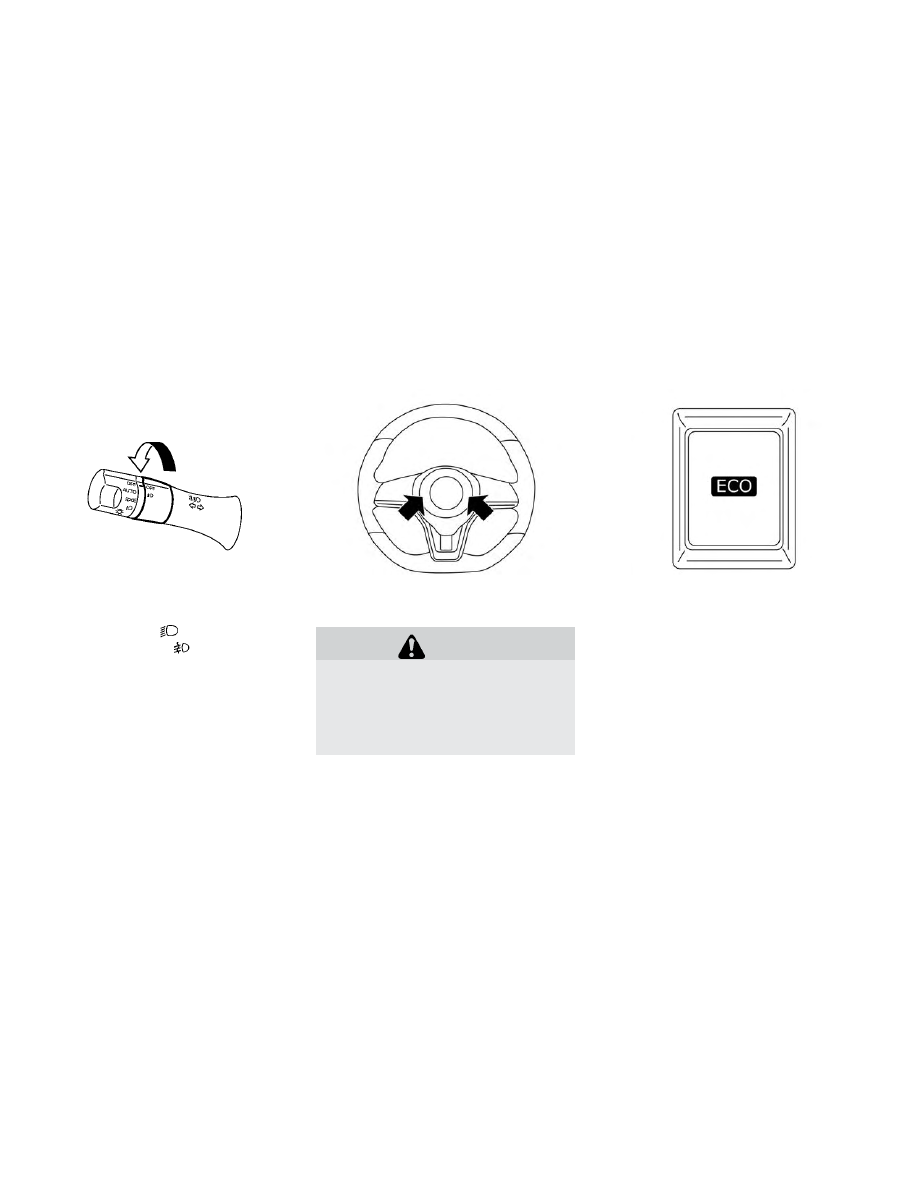
To turn the fog lights on, rotate the head-
light switch to the

position, then ro-

tate the switch to the

position. To turn

them off, rotate the switch to the OFF posi-
tion.

The headlights must be on for the fog
lights to operate.

To sound the horn, push the center pad
area of the steering wheel.

WARNING

Do not disassemble the horn. Doing so
could affect proper operation of the
supplemental front air bag system.
Tampering

with

the

supplemental

front air bag system may result in seri-
ous personal injury.

To turn on the ECO mode, push the ECO
switch. The ECO mode indicator appears
on the meter.

To turn off the ECO mode, push the ECO
switch again. The ECO mode indicator will
turn off.

For additional information, refer to “Electric
shift control system” in the “Starting and
driving” section of this manual

FOG LIGHT SWITCH (IF SO EQUIPPED)

HORN

ECO SWITCH

2-58

Instruments and controls

The front seats and the rear outboard
seats (if so equipped) can be warmed by
built-in heaters. The switches, located on
the center console and at the side of the
front passenger seatback, can be operated
independently of each other.

1. Place the power switch in the ON

position.

2. Push the LO or HI position of the switch,

as desired, depending on the tempera-
ture. The indicator light in the switch will
illuminate.

3. To turn off the heater, return the switch

to the level position. Make sure the indi-
cator light goes off.

The heater is controlled by a thermostat,
automatically turning the heater on and
off. The indicator light will remain on as long
as the switch is on.

When the vehicle’s interior is warmed, or
before you leave the vehicle, be sure to turn
the switch off.

NOTE:

The heated seats consume less power
than the heater and can be used to either
help extend vehicle range by reducing
heater use or to maximize comfort by
supplementing the heater.

WARNING

Do not use or allow occupants to use
the seat heater if you or the occupants
cannot monitor elevated seat tem-
peratures or have an inability to feel
pain in those body parts in contact
with the seat. Use of the seat heater by
such people could result in serious in-
jury.

Rear

HEATED SEAT SWITCHES (IF SO
EQUIPPED)

Instruments and controls

2-59

CAUTION

• Do not use the seat heater for ex-

tended periods or when no one is
using the seat.

• Do not put anything on the seat

which insulates heat, such as a blan-
ket, cushion, seat cover, etc. Other-
wise, the seat may become over-
heated.

• Do not place anything hard or heavy

on the seat or pierce it with a pin or
similar object. This may result in
damage to the heater.

• Any liquid spilled on the heated seat

should be removed immediately
with a dry cloth.

• When cleaning the seat, never use

gasoline, thinner, or any similar ma-
terials.

• If any malfunctions are found or the

heated seat does not operate, turn
the switch off and have the system
checked. It is recommended that
you visit a NISSAN certified LEAF
dealer for this service.

The heated steering wheel system is de-
signed to operate only when the surface
temperature of the steering wheel is below
approximately 68°F (20°C).

Push the heated steering wheel switch to
warm the steering wheel when the power
switch is in the ACC or ON position. The indi-
cator light

1

on the switch will illuminate.

If the surface temperature of the steering
wheel is below approximately 68°F (20°C),
the system will heat the steering wheel and
cycle off and on to maintain a temperature
above 68°F (20°C). The indicator light will
remain on as long as the system is on.

Push the switch again to turn the heated
steering wheel system off manually. The
indicator light turns off.

NOTE:

• If the surface temperature of the steer-

ing wheel is above 68°F (20°C) when the
switch is turned on, the system will not
heat the steering wheel. This is not a
malfunction.

• If the outside temperature is low (ap-

proximately 50°F (10°C) or less) and the
Climate Control Timer or Remote Cli-
mate Control are used, the steering
wheel heater will automatically operate
in the following conditions.

– When using the Climate Control

Timer: Operates from approximately
15 minutes before the set departure
time until the set departure time.

– When using Remote Climate Control:

Operates 15 minutes after Remote
Climate Control starts.

• The heated steering wheel consumes

less power than the heater and can be
used to either help extend vehicle range
by reducing heater use or to maximize
comfort by supplementing the heater.

HEATED STEERING WHEEL SWITCH
(IF SO EQUIPPED)

2-60

Instruments and controls

The E-call (SOS) system switch is used in
combination with a NissanConnect® (for
Leaf) Services subscription to call for assis-
tance in case of an emergency.

Pushing the switch will (with a paid sub-
scription) reach a Response Specialist that
will provide assistance based on the situa-
tion described by the vehicle’s occupant.
For additional information, or to enroll your
vehicle,

refer

to

www.NissanUSA.com/

connect or call 855–426–6628.

To open the charge port lid, push the
charge port lid switch. For additional infor-
mation, refer to “Charge port lid” in the “Pre-
driving checks and adjustments” section of
this manual.

To turn off the charge timer, push the im-
mediate charge switch. For additional in-
formation, refer to “Charging timer” in the
“Charging” section of this manual.

E-CALL (SOS) SWITCH (IF SO
EQUIPPED)

CHARGE PORT LID SWITCH

IMMEDIATE CHARGE SWITCH

Instruments and controls

2-61

The Steering Assist switch is used to turn
on and off the Steering Assist system and
the Intelligent Cruise Control (ICC) system
that is activated using the settings menu of
the vehicle information display.

The Steering Assist system controls the
steering system to help keep your vehicle
near the center of the lane when driving.
The Steering Assist system is combined
with the Intelligent Cruise Control (ICC). For
additional information, refer to “Intelligent
Cruise Control (ICC) with ProPILOT Assist)” in
the “Starting and driving” section of this
manual.

CAUTION

• The outlet and plug may be hot dur-

ing or immediately after use.

• Do not use with accessories that ex-

ceed a 12-volt, 120W (10A) power
draw.

• Do not use double adapters or more

than one electrical accessory.

• Use the power outlet with the power

switch is in the ON or Ready to Drive
position to avoid discharging the 12-
volt battery.

• Avoid using the power outlet when

the air conditioner, headlights or
rear window defroster are on.

• This power outlet is not designed for

use with a cigarette lighter unit.

• Push the plug in as far as it will go. If

good contact is not made, the plug
may overheat or the internal tem-
perature fuse may open.

• Before inserting or disconnecting a

plug, make sure that the electrical
accessory being used is turned OFF.

• When not in use, be sure to close the

cap. Do not allow water to contact
the outlet.

STEERING ASSIST SWITCH (IF SO
EQUIPPED)

POWER OUTLET

2-62

Instruments and controls

SEATBACK POCKET (IF SO
EQUIPPED)

The seatback pockets may be located on
the driver’s and/or passenger’s seat.. The
pocket can be used to store maps.

WARNING

To ensure proper operation of the pas-
senger’s NISSAN Advanced Air Bag
System, please observe the following
items:
• Do not allow a passenger in the rear

seat to push or pull on the seatback
pocket or head restraint.

• Do not place heavy loads heavier

than 9.1 lbs. (4 kg) on the seatback,
head restraint, or in the seatback
pocket.

STORAGE TRAY

WARNING

Do not place sharp objects in the
tray(s) to help prevent injury in an acci-
dent or sudden stop.

Instrument panel

STORAGE

Instruments and controls

2-63

GLOVE BOX

To open the glove box, pull the handle.

To close, push the lid in until it latches.

WARNING

Keep the glove box lid closed while
driving to prevent injury in case of an
accident or a sudden stop.

CONSOLE BOX

To open the console box, pull up the lever

A

and pull up the lid. To close, push the lid

down until it is latched.

OVERHEAD SUNGLASSES
STORAGE

To open the sunglasses holder, push and
release. Only store one pair of sunglasses
in the holder.

WARNING

Keep the sunglasses holder closed
while driving to avoid obstructing the
driver’s view and to help prevent an
accident.

2-64

Instruments and controls

CAUTION

• Do not use for anything other than

sunglasses.

• Do not leave sunglasses in the sun-

glasses holder while parking in di-
rect sunlight. The heat may damage
the sunglasses.

CUP HOLDERS

WARNING

Avoid abrupt starting and braking
when the cup holder is being used to
prevent spilling the drink. If the liquid is
hot, it can scald you or your passenger.

CAUTION

Use only soft cups in the cup holder.
Hard objects can injure you in an acci-
dent.

Front

Soft bottle holder (front)

Soft bottle holder (rear)

Instruments and controls

2-65

CAUTION

• Do not use the bottle holder for any

other objects that could be thrown
about in the vehicle and possibly in-
jure people during sudden braking
or an accident.

• Do not use the bottle holder for open

liquid containers.

TONNEAU COVER (IF SO
EQUIPPED)

WARNING

• Never put anything on the tonneau

cover, no matter how small. Any ob-
ject on it could cause an injury in an
accident or sudden stop.

• Do not leave the tonneau cover in

the vehicle with it disengaged from
the holder.

• Properly secure all cargo with ropes

or straps to help prevent it from slid-
ing or shifting. Do not place cargo
higher than the seatbacks. In a sud-
den stop or collision, unsecured
cargo could cause personal injury.

• Properly secure cargo and do not al-

low it to contact the top tether strap
when it is attached to the top tether
anchor. Cargo that is not properly
secured or cargo that contacts the
top tether strap may damage the
top tether strap during a collision. If
the cargo cover contacts the top
tether strap when it is attached to
the top tether anchor, remove the
cargo cover from the vehicle or se-
cure it on the cargo floor below its
attachment location. If the cargo
cover is not removed, it may damage
the top tether strap during a colli-
sion. Your child could be seriously in-
jured or killed in a collision if the
child restraint top tether strap is
damaged.

The tonneau cover keeps the luggage
compartment contents hidden from the
outside.

To remove the tonneau cover:

1. Remove the straps from the rear hatch.

2. Pull up the tonneau cover.

3. Remove the tonneau cover holders

from the rear pillar.

2-66

Instruments and controls

4. Slide down the tonneau cover along the

rear seat back.

5. Remove the tonneau cover by pulling

either the left or right side backward
away from the pillar.

STOWING GOLF BAGS

Normally, two standard golf bags can be
stowed in the cargo area. Insert the top of
the golf bag into the right side of the cargo
area

1

then rotate the bag backward

2

.

Insert the top of the second golf bag into
right side of the cargo area

3

and stow the

bottom of golf bag forward all the way

4

.

In some cases, you may not be able to stow
two golf bags in your vehicle, depending on
their sizes or types.

POWER WINDOWS

WARNING

• Make sure that all passengers have

their hands, etc. inside the vehicle
while it is in motion and before clos-
ing the windows. Use the window
lock switch to prevent unexpected
use of the power windows.

• To help avoid risk of injury or death

through unintended operation of the
vehicle or its systems, including en-
trapment in windows or inadvertent
door lock activation, do not leave chil-
dren, people who require the assis-
tance of others, or pets unattended in
your vehicle. Additionally, the tem-
perature inside a closed vehicle on a
warm day can quickly become high
enough to cause a significant risk of
injury or death to people and pets.

The power windows operate when the
power switch is in the ACC or ON position,
or for about 45 seconds after the power
switch is placed in the OFF position. If the
driver’s or front passenger’s door is opened
during this period of about 45 seconds,
power to the windows is canceled.

WINDOWS

Instruments and controls

2-67

Main power window switch
(driver's side)

1. Driver side window
2. Front passenger side window
3. Rear left passenger side window
4. Rear right passenger side window
5. Window lock button

To open or close a window, push down

A

or pull up

B

the corresponding switch and

hold it. The main switches, on the driver's
side, will open or close all the windows.

Locking passengers' windows

When the lock button

C

is pushed in, only

the driver side window can be opened or
closed. Push it in again to cancel.

Passenger side power window
switch

The

passenger's

side

power

window

switch will open or close only the corre-
sponding window. To open or close the
window, push down or pull up the switch
and hold it.

Rear power window switch

The rear power window switches open or
close only the corresponding windows. To
open the window, push the switch and hold
it down. To close the window, pull the
switch up.

2-68

Instruments and controls

Automatic operation

The automatic operation is available for
the switch that has an

mark on its

surface.

To fully open or close the window, com-
pletely push down or pull up the switch and
release it; the switch need not be held. The
window will automatically open or close all
the way. To stop the window, just push or lift
the switch in the opposite direction.

A light push or pull on the switch will cause
the window to open or close until the
switch is released.

Auto-reverse function

WARNING

There are some small distances imme-
diately before the closed position
which cannot be detected. Make sure
that all passengers have their hands,
etc., inside the vehicle before closing
the window.

If the control unit detects something
caught in the window as it is closing, the
window will be immediately lowered.

The auto reverse function can be activated
when the window is closed by automatic
operation when the power switch is in the
ON position or for 45 seconds after the
power switch is placed in the OFF position.

Depending on the environment or driv-
ing conditions, the auto reverse function
may be activated if an impact or load
similar to something being caught in the
window occurs.

If the windows do not close
automatically

If the power window automatic function
(closing only) does not operate properly,
perform the following procedure to initial-
ize the power window system.

1. Place the power switch in the ON

position.

2. Close the door.

3. Open the window completely by operat-

ing the power window switch.

4. Pull the power window switch and hold

it to close the window, and then hold the
switch more than 3 seconds after the
window is closed completely.

5. Release the power window switch. Op-

erate the window by the automatic
function to confirm the initialization is
complete.

If the power window automatic function
does not operate properly after perform-
ing the procedure above, have your vehicle
serviced. It is recommended that you visit a
NISSAN certified LEAF dealer for this ser-
vice.

Instruments and controls

2-69

The interior lights can be turned on

1

re-

gardless of door position. The lights will go
off after a period of time unless the power
switch is placed in the ON position when
any door is opened.

The interior lights can be set to operate
when the doors are opened

2

. To turn off

the interior lights when a is door open,
push the switch; the interior lights will not
illuminate, regardless of door position.

The lights will go off when the power switch
is placed in the ON position, or the driver’s
door is closed and locked. The lights will
also go off after a period of time when the
doors are open.

CAUTION

Do not use for extended periods of
time with the power switch in the OFF
position. This could result in a dis-
charged 12-volt battery.

CONSOLE LIGHT (IF SO EQUIPPED)

The console light will turn on whenever the
parking lights or headlights are illuminated.

The console light brightness can be ad-
justed with the illumination brightness
control in the vehicle information display.

MAP LIGHTS

Press the button to turn the map lights on.
To turn them off, press the button again.

INTERIOR LIGHTS

2-70

Instruments and controls

ROOM LIGHT

The room light switch has three positions:
ON, DOOR and OFF.

ON position

When the switch is in the ON position

1

,

the ceiling light will illuminate.

DOOR position

When the switch is in the DOOR position

2

,

the ceiling light will illuminate under the
following conditions:

• the power switch is placed in the LOCK

position

– remains on for about 15 seconds.

• doors are unlocked by pushing the

UNLOCK

button or the request

switch, with the power switch in the LOCK
position

– remains on for about 15 seconds.

• any door is opened and then closed with

the power switch in the LOCK position

– remains on for about 15 seconds.

• any door is opened while the power

switch in the ACC or ON position

– remains on while the door is opened.

When the door is closed, the light turns
off.

The light will automatically turn off after
10 minutes when the light remains illu-
minated to prevent the battery from be-
coming discharged.

OFF position

When the switch is in the OFF position

3

,

the ceiling light will not illuminate, regard-
less of the condition.

CARGO LIGHT

The light illuminates when the rear hatch is
opened. When the rear hatch is closed, the
light goes off. For additional information,
refer to “Exterior and interior lights” in the
“Maintenance and do-it-yourself ” section
of this manual.

Instruments and controls

2-71

The HomeLink® Universal Transceiver pro-
vides a convenient way to consolidate the
functions of up to three individual hand-
held transmitters into one built-in device.

HomeLink® Universal Transceiver:

• Will operate most Radio Frequency (RF)

devices such as garage doors, gates,
home and office lighting, entry door locks
and security systems.

• Is powered by the vehicle’s 12-volt battery.

No separate batteries are required. If the
vehicle’s 12-volt battery is discharged or is
disconnected, HomeLink® will retain all
programming.

Once the HomeLink® Universal Trans-
ceiver is programmed, retain the original
transmitter

for

future

programming

procedures (for example, new vehicle
purchases). Upon sale of the vehicle, the
programmed HomeLink® Universal Trans-
ceiver buttons should be erased for secu-
rity purposes. For additional information,
refer to “Programming HomeLink®” in this
section.

WARNING

• Do not use the HomeLink® Universal

Transceiver with any garage door
opener that lacks safety stop and re-
verse features as required by federal
safety standards. (These standards
became effective for opener models
manufactured after April 1, 1982.) A
garage door opener that cannot de-
tect an object in the path of a closing
garage door and then automatically
stop and reverse, does not meet cur-
rent federal safety standards. Using
a garage door opener without these
features increases the risk of serious
injury or death.

• During the programming procedure,

your garage door or security gate
will open or close (if the transmitter
is within range). Make sure that
people or objects are clear of the ga-
rage door, gate, etc. that you are pro-
gramming.

• Place the power switch in the ACC or

ON position while programming the
HomeLink® Universal Transceiver.

PROGRAMMING HOMELINK®

If you have any questions or are having
difficulty programming your HomeLink®
buttons, refer to the HomeLink® web site at:
www.homelink.com or call 1-800-355-3515.

NOTE:

Place the power switch in the ACC posi-
tion when programming HomeLink®. It is
also recommended that a new battery
be placed in the hand-held transmitter
of the device being programmed to
HomeLink® for quicker programming
and

accurate

transmission

of

the

radio-frequency.

1. Position the end of your hand-held

transmitter 1–3 inches (2–8 cm) away
from the HomeLink® surface, keeping
the HomeLink® indicator light

1

in view.

HOMELINK® UNIVERSAL
TRANSCEIVER (IF SO EQUIPPED)

2-72

Instruments and controls

2. Using both hands, simultaneously press

and hold the desired HomeLink® button
and handheld transmitter button. DO
NOT release until the HomeLink® indica-
tor light

1

flashes slowly and then rap-

idly. When the indicator light flashes
rapidly, both buttons may be released.
(The rapid flashing indicates successful
programming.)

NOTE:

Some devices may require you to re-
place Step 2 with the cycling proce-
dure noted in the “Programming
HomeLink® for Canadian customers
and gate openers” section.

3. Press

and

hold

the

programmed

HomeLink® button and observe the indi-
cator light.

• If

the

indicator

light

1

is

solid/

continuous, programming is com-
plete 
and your device should activate
when the HomeLink® button is pressed
and released.

• If the indicator light

1

blinks rapidly for

two seconds and then turns to a
solid/continuous light, continue with
Steps 4-6 
for a rolling code device. A
second person may make the following
steps easier. Please use a ladder or
other device. Do not stand on your ve-
hicle to perform the next steps.

Instruments and controls

2-73


Content   ..  12  13  14  15   ..