Lexus ES300 (2002 year). Service manual - part 21
184
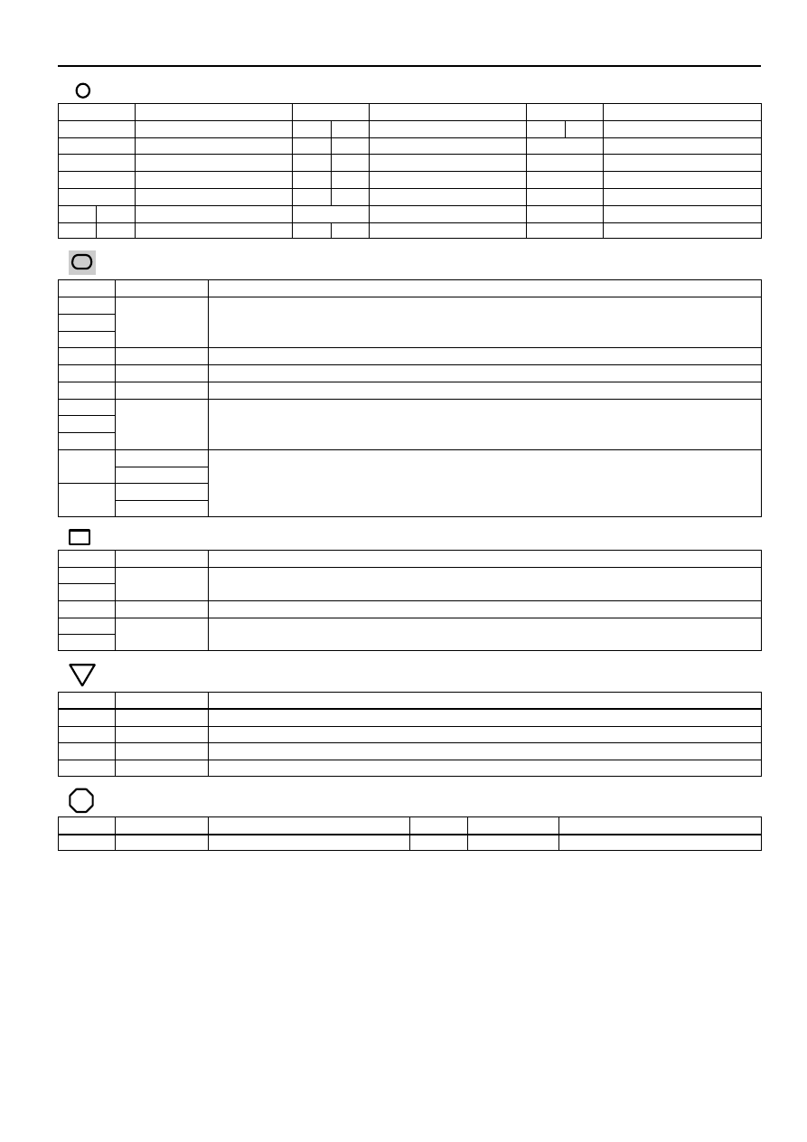
Cruise Control
: Parts Location
Code
See Page
Code
See Page
Code
See Page
A4
E6
A
S7
C
A25
E7
B
S13
C7
E8
C
T2
C10
E9
D
T3
D2
E10
E
T8
E1
A
J11
E2
B
S6
B
: Junction Block and Wire Harness Connector
Code
See Page
Junction Block and Wire Harness (Connector Location)
1B
1C
Engine Room Main Wire and Engine Room J/B (Engine Compartment Left)
1H
g
g
(
g
)
1K
Engine Wire and Engine Room J/B (Engine Compartment Left)
2B
Instrument Panel Wire and Driver Side J/B (Lower Finish Panel)
2G
Engine Room Main Wire and Driver Side J/B (Lower Finish Panel)
2M
2O
Instrument Panel Wire and Driver Side J/B (Lower Finish Panel)
2P
(
)
3A
3A
Instrument Panel Wire and Passenger Side J/B (Instrument Panel Brace RH)
3B
Instrument Panel Wire and Passenger Side J/B (Instrument Panel Brace RH)
3B
: Connector Joining Wire Harness and Wire Harness
Code
See Page
Joining Wire Harness and Wire Harness (Connector Location)
IF4
Engine Room Main Wire and Instrument Panel Wire (Right Side of Steering Column Tube)
IF5
Engine Room Main Wire and Instrument Panel Wire (Right Side of Steering Column Tube)
IK1
Instrument Panel Wire and Instrument Panel Wire (Instrument Panel Reinforcement RH)
IL1
Engine Wire and Instrument Panel Wire (Behind the Glove Box)
IL2
Engine Wire and Instrument Panel Wire (Behind the Glove Box)
: Ground Points
Code
See Page
Ground Points Location
ED
Left Fender
EE
Left Side of Cylinder Head
EF
Intake Side of Cylinder Block
ID
Instrument Panel Brace RH
: Splice Points
Code
See Page
Wire Harness with Splice Points
Code
See Page
Wire Harness with Splice Points
I2
Engine Room Main Wire
I6
Engine Wire