Lexus ES300 (2002 year). Service manual - part 19
176
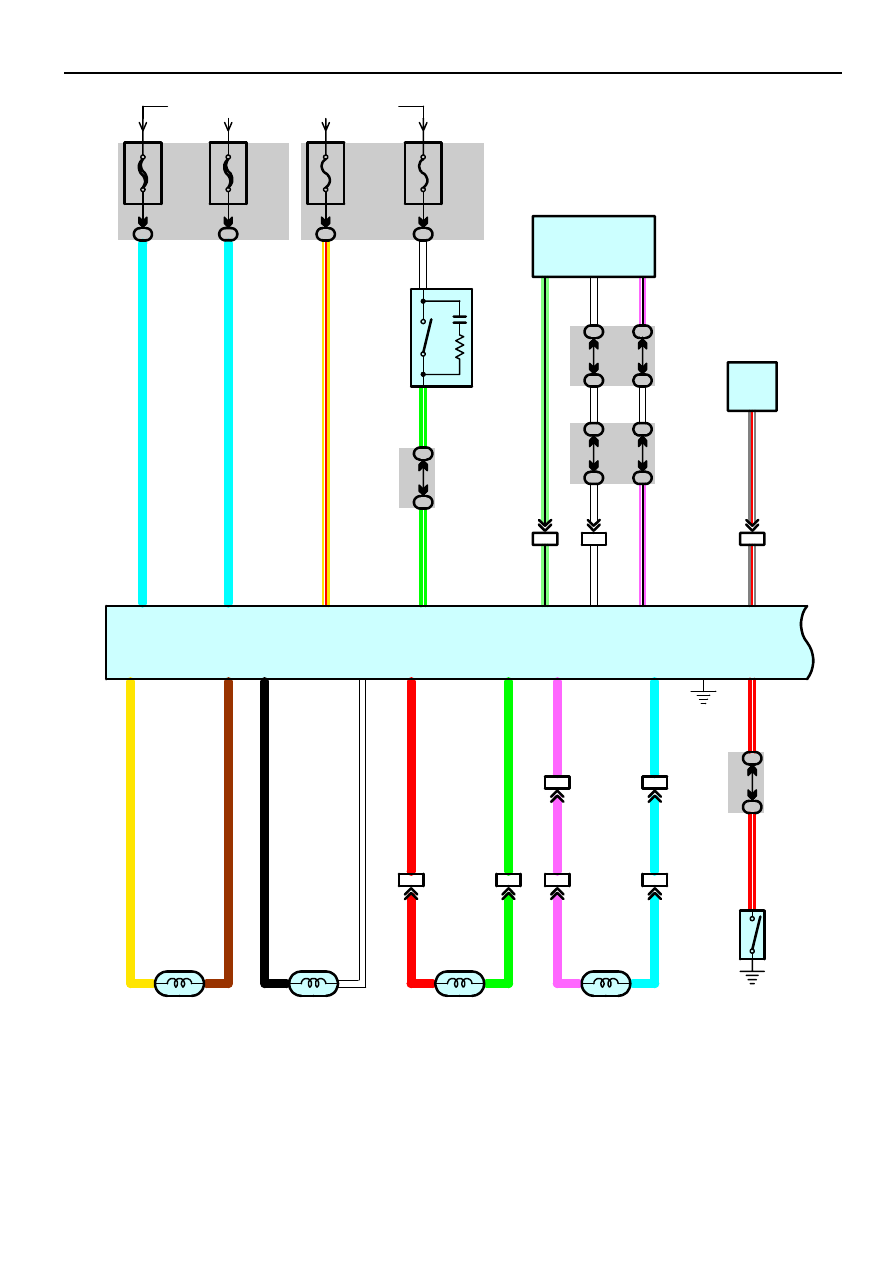
ABS
10A
ECU–IG
2G
21
From Power Source System (See Page 56)
1G
ID1
13
2
1
ID1
3
IF4
8
2
1
IF4
9
IO5
14
IO5
15
1
2
1
2
2G
11
2G
23
15A
STOP
2G
13
IF4
21
3B
52
3B
42
2G
7
2G
19
L
L
Y–
R
W
G–
W
G–
W
W
P–
B
LG
–
B
P–
B
R
G
P
L
R
G
P
L
P
L
B
W
Y
BR
R–
W
R–
W
25
23
1
10
14
16
14
13
11
12
33
34
30
31
8
9
18
Data Link Connector 3
D 2
Skid Control ECU with Actuator
S 1
ABS Speed Sensor
Rear LH
A36
ABS Speed Sensor
Rear RH
A37
ABS Speed Sensor
Front RH
A 7
ABS Speed Sensor
Front LH
A 6
W
3B
51
3B
41
TS
TC
1
2
1
2
40A
ABS
NO. 3
2
40A
ABS
NO. 2
1
1
1E
7
IF7
LG
–B
15
SIL
W
7
18 2G
3 2L
2L
4
2P
4
W
W
S
top
Li
g
h
t S
W
S1
3
P
a
rk
ing B
rak
e S
W
P 5
H
e
a
d
lig
h
t B
eam
Lev
el
Co
n
tr
o
l E
C
U
H1
4
IF8
3
20
G
R
–R
G
R
–R
26
SPDR
(*1
)
(*1
)
7
5
FL–
FL+
FR–
FR+
RL+
RL–
RR+
RR–
PKB
+BM
+BS
IG1
STP
TS
D/G
TC
FRO