Lexus ES300 (2002 year). Service manual - part 20
180
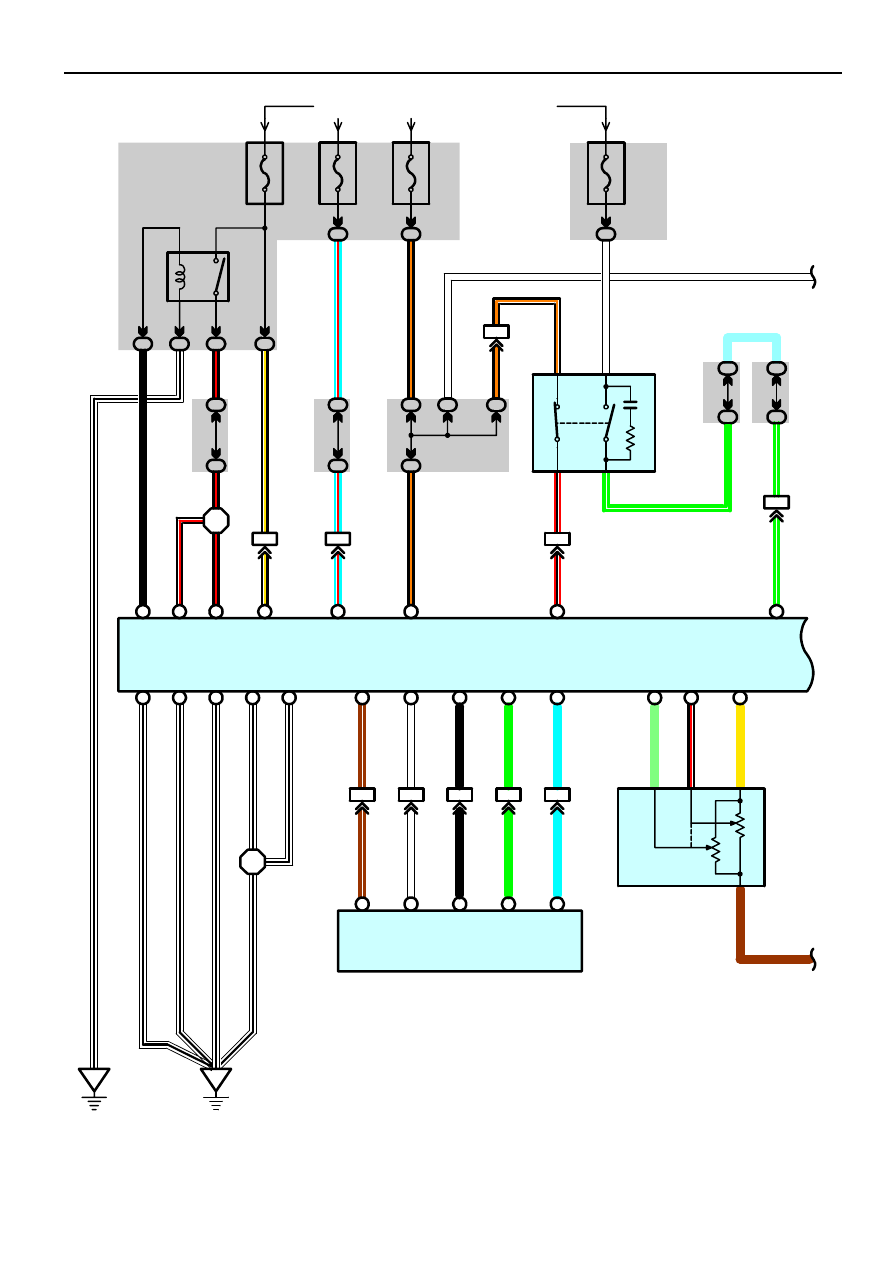
Cruise Control
20A
EFI
1B
9
10A
IG2
From Power Source System (See Page 56)
1C
7
IF5
7
3A
51
3A
91
B
2
A
9
2
3
1
5
1C
4
1C
5
2G
5
2G
17
A
2
ED
1B
3
A
8
E
7
E
6
C
4
D
7
D
6
EE
I 6
B
19
IK1
7
2M
4
2G
7
15A
STOP
2G
13
E
18
E
31
E
21
2
3
1
BR
W–
B
W–
B
W–
B
W–
B
W–
B
W
–
B
W–
B
W–
B
W–
B
W–
B
B–
W
W–
B
B–
W
B–
R
B–
Y
B–
R
B–
Y
B–
O
B
–
O
G–
W
G
–
W
W
BR
LG
B–
R
Y
G–W
SB
Engine Control Module
E 6(A), E 7(B), E 8(C), E 9(D), E10(E)
S
top
Li
g
h
t S
W
S1
3
T
h
ro
tt
le
P
o
s
iti
on
S
e
n
so
r
T 3
E01
E02
ME01
E04
E05
VTA1
VTA2
VC
MREL
+B1
BATT
IGSW
STP
4
EF
I R
e
la
y
1
2
I 2
A
1
B–
R
+B
B–
R
2G
8
2G
20
VC
E2
VTA
VTA2
B–
O
4
3
2P
5
B–
O
IF4
12
IF5
5
B
12
R–
B
ST1–
R–
B
A
31
L
TRC–
A
25
G
TRC+
ENG–
B
30 A
A
24
W
ENG+
NEO
BR
–
W
17 A
IF4
22
IF4
7
IF4
8
IF4
9
IF4
10
NEO
ENG+
ENG–
TRC+
TRC–
L
W
B
G
BR
–
W
B
26
C
9
C
18
C
11
C
20
Skid Control ECU
S 6(B), S 7(C)
2O
W
5
10A
ETCS
1B
2
IL2
1
B
6
L–
R
L–
R
+BM
W
L–
R
1H
4
1K
9